Model Railways-Planbooks - books with scale diagrams and plans in them
[Navigating the page: To find an individual reference, locomotive, station, railway, carriage, model, etc., please use CTRL + F to take you right to the place where it is mentioned]
Stations and Carriages are on separate pages
| Related Model Railway Author Pages of Interest: |
Related Model Railway Topic Areas Pages of Interest: |
|
|
|
****Hyperlinked titles will take you to our copy on sale or prebuilt searches of copies on sale****
Useful Links:
Books on Ebay-see our specially prebuilt search below of 4mm scale planbooks
Books on Amazon-see our specially prebuilt search banner of 4mm scale planbooks
Titles Listed Below with images, descriptions, and availability (including pricing):
[in order of title, click to go to full listing below. Date indicates earliest edition; listings include later editions]
1983. 19th Century Railway Drawings in 4mm Scale
1994. The 4mm Coach: Part One-first principles and basic projects by Stephen Williams
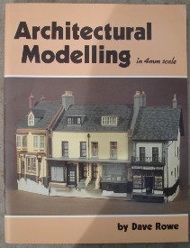
1983. Architectural Modelling in 4mm Scale by Dave Rowe
1981. B. R [British Railways] Standard Locomotives to Scale [4mm] by Ian Beattie
1963 (& later editions). British Rail Main-Line Diesels: Revised and Enlarged Edition by S. W. Stevens-Stratten & R. S. Carter (drawings)
1991. British Rail Main Line Diesel Locomotives by Colin Marsden and Graham B. Fenn
1968. Building Model Locomotives by F. J. Roche and G. G. Templer; edited by S. W. Stevens-Stratten
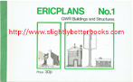
1971. ERICPLANS. No. 1. GWR Buildings and Structures by Eric Ilett
1977. ERICPLANS. GWR & LMS Buildings and Structures by Eric Ilett
1971. ERICPLANS. LMS (London, Midland, Scottish) Buildings and Structures (Ericplans No. 2) by Eric Ilett
1971. ERICPLANS No. 5. GWR Buildings and Structures
1981. G.W.R. Locomotives To Scale [4mm] by Ian Beattie
1974. Historic Carriage Drawings in 4mm Scale: Vol 1. LMS and LNER
1998. Historic Carriage Drawings. Volume Two: LMS and Constituents by David Jenkinson
c1971. Historic Locomotive Drawings in 4mm Scale drawn by F. J. Roche
1978. Historic Wagon Drawings in 4mm Scale drawn by F. J. Roche
1981. L.M.S.R. Locomotives to Scale by Ian Beattie
1981. L.N.E.R Locomotives to Scale by Ian Beattie
1949. Locomotives Worth Modelling
1984. Midland Railway Carriages: Volume One by R. E. Lacy and George Dow. [Contains many scale diagrams & photos]
1988. Model Locomotive Boilermaking by Alec Farmer
1984. Model Railway Constructor Planbook 2: BR Mainline Diesels in 4mm Scale
1985. Model Railway Constructor Planbook 3: BR Electric Locomotives in 4mm Scale by Russell S. Carter
1948. Modelling 4mm. Scale Rolling Stock by Michael Longridge
2003. Modelling Aspects of the Coal Industry by Rob Johnson
2006. Modelling Further Aspects of the Coal Industry by Rob Johnson
1996. Modelling Diesels in 4mm Scale: RTR conversions and Improvements by Tim Shackleton
1949. Painting and Lining Models by R. C. Rogers
1975. Plans Handbook 2: Model Boats & Cars
1974. Plans Handbook 3: Model Engineering
1973. Private-Owner Wagons by Peter Matthews
1981. Southern Locomotives To Scale [4mm] by Ian Beattie
1940. Valves & Valve Gears for Steam Locomotives by G.S. Lake and A. Reidinger
Useful Model Engineering & Model Railway Pages Elsewhere on the Site:
Gears
K. N. Harris (useful on model boilers and boilermaking)
LBSC
Martin Evans - model engineering guru
Milling Machines & Lathes
Model Engineering-catalogues (e.g. model engineering shop catalogues)
Model Railway Books on Ebay
Model Railway Building - build your layout - find the books to help you do this
Model Railways-Planbooks
Percival Marshall Publications (well known for their mechanical, engineering & model engineering focus)
Stationary Steam Engines
Useful Pages Elsewhere on the Internet:
[Slightly Better Books is not responsible for the content of external internet sites]
http://www.modelsteamtrains.com - takes you to a prebuilt search (built by us) on Ebay for model steam locos
http://www.reeves2000.co.uk - one of the world's largest model engineers supplying parts, valves, castings, boilers, plans, books, screws, nuts, tools, solder, fluxes, brazing equipment, etc
http://www.southernregion.co.uk - takes you to a prebuilt search (built by us) on Ebay for model trains pertaining to the Southern Region
http://www.teepublishing.co.uk - TEE Publishing, supplier of new and out of print books and magazines for model engineers
http://www.weatheredtrains.co.uk - takes you to a prebuilt search (built by us) on Ebay for model trains (locomotives, carriages and wagons) with a weathered look
Railway Locomotive Classes - web pages built by Slightly Better Books
Class 20 -takes you to a prebuilt search (built by us) on Ebay for items related to the class 20 locomotive, including model locomotives and genuine railwayana
Class 33 -takes you to a prebuilt search (built by us) on Ebay for items related to the class 33 locomotive, including model locomotives and genuine railwayana
Class 58 -takes you to a prebuilt search (built by us) on Ebay for items related to the class 58 locomotive, including model locomotives and genuine railwayana
Class 73 -takes you to a prebuilt search (built by us) on Ebay for items related to the class 73 locomotive, including model locomotives and genuine railwayana
***Please note that we only sell books of scale drawings (see below)***
If you're looking for a particular technical drawing/scale drawing of a locomotive, wagon, carriage, rolling stock, you should try our prebuilt Ebay search for technical railway drawings . For example:
|
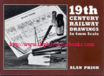
1983, David & Charles, hbk
Sorry, sold out, but click image above to access prebuilt search for this title on Amazon UK
Alternative online retailers to try:
Click here to access our prebuilt search for this title on Abebooks
Or click here to access our prebuilt search for this title on Alibris
Or click here to access our prebuilt search for this title on Ebay


|
- 19th Century Railway Drawings in 4mm Scale [top]
Written by Alan Prior
First published in 1983 in Great Britain in hardback with dustjacket, 96pp, ISBN 0715380060 . Jacket photograph and model by Brian Meredith . Jacket photograph and model by Brian Meredith
Modellers should note the following:
- that it was not always the case that locomotives were built exactly as specified by the plan: rebuilds and modifications may have changed the locomotives' designs and specifications, not to mention their appearance
- There are few photographs of this era because much of it was prior to the invention of photography. The first known railway photograph is from 1849
- All drawings are on the 4mm-1ft scale. Scales and dimensions are provided, so modellers in other scales should not have any problems with conversion into their scales
- All dimensions on the plans are in feet and inches unless otherwise specified and all plans have been prepared for use by amateur modelmakers with detail limited to what can reasonably be incorporated
- All drawings represent full size originals and modellers will need to make appropriate adjustments, particularly allowances for overscale flanges
- 00 gauge is under gauged for true 4mm to an equivalent of 4ft 2 inches
About this book/synopsis: Horizons have widened for railway modellers over the last two or more decades and prior to this book's publication, the developing use of scenic modelling techniques means that there are now a huge variety of subjects and settings in today's model railways in the quest not only for originality, but also in period modelling. Many model railways reproduce the most intricate and fondly remembered microcosm of social history complete with engines, coaches, signalling, buildings, and modelled life, all of which combine to portray all the features of a given moment in time.
But for those modellers wishing to reproduce railways of the formative years of railway construction and enterprise in the 19th Century, there are considerable difficulties finding easily available references and getting hold of the right ones for the layout desire is time consuming: time that would be better spent designing and building the layout.
While research into archives or publications for drawings of the past may be fun, not everyone wants to undertake this and in 'Nineteenth Century Railway Drawings in 4mm Scale' Alan Prior has prepared from a variety of sources a widely representative selection of drawings. All have been reproduced to the standard British 4mm scale for 00 gauge or the finer scale EM and Protofour derivatives, of locomotives, rolling stock, signalling and track of many companies in the period from the 1820s, as the Stockton & Darlington Railway opened, to the end of the century when Atlantic and 4-6-0 locomotives had just appeared, and bogie coaches were becoming common.
Between are a wide variety of locomotives and stock of the early trunk lines, including the Great Western Broad Gauge, and the developments including improved track and signalling of mid-Victorian years. The drawings, which are finely detailed, with dimensions, will provide modellers and students of the Victorian railway scene with a substantial appetiser which, it is hoped, will encourage them to delve more deeply into railways a century ago.
Contents:
Introduction
1. Chauldron, flat and construction wagons, c. 1800
2. Killingworth Colliery Locomotive by George Stephenson, c.1820
3. S&DR 0-4-0 locomotive and tender Locomotion by Messrs Stephenson & Co., 1825 (as preserved); S&DR 0-6-0 locomotive and tenders 'Royal George' by Timothy Hackworth, 1827
4. S&DR Carriage and Wagon, c.1825
5. L&BR 2-2-0 locomotive and tender by Bury, 1838
6. C&BR and M&LR first class carriages, c.1840 and c.1839 etc
7. M&LR second and third class carriages, c.1839
8. M&LR open goods wagon, c.1839, and M&BR coal wagon, c.1839; etc
9. Iron rails, switch, and policemen's signals, c.1830 2-2-2 locomotive and tender by Robert Stephenson, c.1840
10. S&DR 0-6-0 locomotive and tenders Wilberforce by R. & W. Hawthorn, 1831
11. GWR 4-4-0 tank locomotive Corsair by Daniel Gooch (broad gauge), 1849
12. GWR (2+2)-2-2 locomotive and tender Iron Duke by Daniel Gooch (broad gauge), 1848
13. GWR 0-6-0 locomotive and tender Pyracmon by Daniel Gooch (broad gauge), 1848
14. GWR six-wheeled first class carriage (broad gauge), 1846
15. B&ER six-wheeled second class carriage (broad gauge), 1846
16. GWR six-wheeled third class carriage (broad gauge), c.1845
17. GWR six-wheeled luggage brake van (broad gauge), c.1845
18. GWR carriage truck and horse box (broad gauge), 1840 & 1849
19. GWR covered wagon and B&ER goods brake van (broad gauge), 1856 & c.1850
20. GWR goods & cattle (tilt) wagon and open box wagon (broad gauge), 1848 & c.1848
21. GWR coal and coke wagons (broad gauge), 1854 & 1858
22. GWR signal, and switch and crossing (broad gauge), c.1850
23. LNWR (2+2+2)-2-0 locomotive and tender Liverpool by T.R. Crampton, c.1848
24. LNWR (GJR) 2-2-2 locomotive and tender by A. Allan, 1843/58
25. (2+2)-2-0 locomotive and tender by Robert Stephenson (long boiler), 1846/7
26. SER (2+2)-2-0 locomotive and tender Folkstone by Robert Stephenson, 1848
28. S&DR 0-6-0 locomotive and tenders Derwent by W. & A. Kitching, 1845 (as preserved)
29. MS&LR 0-6-0 locomotive and tender Sphynx by Sharp Brothers & Co, c.1850
30. CR 2-2-2 tank locomotive by Robert Sinclair, c.1850
31. 2-2-0 tank locomotive by Robert Stephenson, c.1850
32. GNR 0-6-0 locomotive and steam tender by Archibald Sturrock, c.1850 and c.1863
33. GNR carriage truck and horse box by Archibald Sturrock, c.1850
34. Four-wheeled first and second class carriages by Brown, Marshall & Co., c.1850
35. Four-wheeled third class carriage and luggage brake van by Brown, Marshall & Co, c.1850
36. ECR eight-wheeled first and second class carriage by W.B. Adams, 1847
37. GWR eight-wheeled first and second
class carriage (broad gauge), 1852
38. GNR mineral brake van and goods brake van, 1850 and 1854
39. GNR coal and coke wagons, c.1850
40. LNWR iron round-end and platform wagons by Henry H. Henson, c.1850
41. LNWR timber and open wagons by Henry H. Henson, c. 1850
42.
LNWR covered goods wagon and gunpowder van by Henry H. Henson, c.1850
43. LNWR cattle and sheep wagons by Henry H. Henson, c.1850
44. LNWR coke wagons by Henry H. Henson, c.1850
45. LNWR coke wagon and goods brake van by Henry H. Henson, c.1850
46. Track, switches and crossings by Fox Henderson & Co., c.1850
47. NBR track, switches and crossings, c.1850
48. Turntable for locomotive and tender by Lloyds, Foster & Co., c.1850
49. Turntables for carriages and wagons, c.1850
50. Signals, c.1850
51. Water Cranes, c.1850
52. LNWR coking apparatus and L&SR shed crane and roof details, c.1850
52. ECR wagon hoist by Peter Ashcroft, c.1850
53. LNWR 2-2-2 locomotive and tender Lady of the Lake by J. Ramsbottom, c.1860
54.
LNWR 0-6-0 locomotive by J. Ramsbottom, c.1860
55. GNSR 4-4-0 locomotive and tender by Neilson & Co., c.1860
56. GS&WR 0-4-4 double bogie tank locomotive by A. A. McDonnell, 1869
57. 0-6-0 tank locomotive by Manning Wardle & Co., 1867
58. NLR 4-4-0 tank locomotive by William Adams, 1868
59. GER first and second class carriage, c.1860, and NLR luggage brake van, c.1870
60. NLR first and second class carriages
c.1870
61. GER round end wagon, c.1865, and GS&WR covered goods wagon, c.1865
62. UR cattle and coal wagons by John Eaton, c.1865
63. Track, switches and crossings by Wild & Parson, c.1865
64. MR 2-4-0 locomotive and tender by S.W.Johnson, 1880
65. GNR 4-2-2 locomotive and tender by Patrick Stirling, 1875
66. GNR six-wheeled milk and fruit brake van, 1886
67. GNR six-wheeled first class corridor lavatory carriage, 1882
67. GNR six-wheeled second class and luggage carriage, 1878
68. GNR six-wheeled first and second class brake carriage, c.1880
69. Drawing room car by Pullman Palace Car Co. for the MR, 1876
70. MR twelve-wheeled bogie first and third class luggage carriage by Thomas Clayton, 1875
71. MR eight-wheeled bogie third class and luggage brake carriage by Thomas Clayton, 1878
72. LNWR eight-wheeled radial brake second and third-class carriage, 1886
73. LNWR eight-wheeled radial tri-composite luggage carraige, c.1889
74. GWR eight-wheeled first and second class luggage carriage (broad gauge), 1889
75. GWR eight-wheeled luggage brake van (broad gauge convertible), c.1890
76. GWR (2+2)-2-2 locomotive and tender (broad gauge), 1880
77. GWR road vehicle wagon and 20 ton truck, 1888 and 1886
78. GER goods brake van and CR 7 ton mineral wagon, 1882
79. L&YR 0-6-2 tank locomotive, 1897
80. HR 4-6-0 locomotive and tender, 1894
81. GNR 4-4-2 locomotive and tender by Ivatt, 1899
82. NER 4-6-0 locomotive and tender, 1899
83. End elevations of locomotives and tender on pages 90-92
84. GNR meat refrigeration wagon and tank wagon, 1897
85. GNR six-wheeled goods brake van, 1890, and GER ballast wagon, 1895
86. NER 30 ton trolley wagon, 1897 |
|
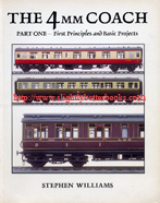
1994, Wild Swan, pbk
Sorry, sold out, but click image above to access prebuilt search for this book on Amazon UK
Alternative online retailers to try:
Click here to access our prebuilt search for this title on Abebooks
Or click here to access our prebuilt search for this title on Alibris
Or click here to access our prebuilt search for this title on Ebay
|
About this book/synopsis: These books have several aims - the first is to place before the reader a detailed guide on coach building and thereby encourage modellers to take a closer and perhaps more discerning look at their own coaching stock to see if they are accurate representations or something less than a perfect attempt. Secondly, by discussing techniques that might be applied to coaches right across the model spectrum from scratch-built to ready-to-run, the author is trying to illustrate ways in which the modeller can produce coaches that really do justice to the prototypes and which will match best efforts elsewhere on the layout - for instance, why get the accuracy of a station layout and setting perfect and then put a lesser standard of coaching stock through it. In summary therefore the book tries to get a best effort standard for the coaching stock no matter what the starting point.
The three volumes in this series have been designed to be read sequentially so that a reader looking through all three books will be able to learn principles and basic practice in volume one (this volume), take on more demanding and sophisticated kits in part two and then turn to scratchbuilt work in volume three.
The first part of each volume considers the basic techniques that are appropriate to the type of approach on which the book is focused and, where appropriate, shows how methods and components discussed in earlier volumes may be refined or improved. Particular problems of dfferent styles o building or types of coach may be discussed. Then, as illustrations, a series of step-by-step projects will be presented, showing different types of coach being constructed, with variations and particular problems examined. The projects are designed to have a dual role - as exercises readers can copy to gain experience and confidence, and to illustrate principles and methods which can be transferred to the specific coaches that the reader wants to build.
The choice of projects is wide and intended to be comprehensive in offering coverage of all the major methods of coach construction and a cross-section of styles of different railway companies from pre-Grouping 6-wheeled stock to early British Railways corridor stock. The books will initially consider modifications to ready-to-run coaches and the simpler pre-formed plastic kits, which together essentially represent the beginner's side of the hobby. But the books will show how high quality carriages can be turned out through careful work on these models.
It's only later on as the books move towards metal and etched kit construction - and scratchbuilding - that the onus begins to be placed on the modeller's ability to shape and form metal and plastic, as well as their ability to work from experience with a minimum of instruction. The author will attempt to pass on as many of their methods as possible, learned over a period of 25 years of building coaches.
Chapters:
1. Introduction, including What Makes a Good Model Coach?; and Basic Tools and Information
2. Ready-to-Run and Plastic Coaches - an outline appraisal
3. Basic Constructional Techniques - the underframe - includes a great black & white photo of the real pressed bogies being constructed at Swindon works (page 14)
4. Basic Constructional Techniques - the body
5. Working with a popular plastic kit - a Midland Railway Lavatory Composite
6. Modifying a Ready-to-Run model - a GWR Corridor Third
7. A More Complex Rebuild - a BR Mark 1 Corridor Composite
8. Gilding a Lilly - a GWR Corridor Third "Toplight"
9. Painting, Lining and Lettering
Appendix: glossary of Terms
Indexed |
|
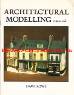
1983, Wild Swan Publications, pbk
In stock, click to buy for £28 (not including p&p, which is Amazon UK's standard charge)
1983, Wild Swan Publications
Alternative online retailers to try:
Click here for our prebuilt search for this book on Abebooks
Click here for our prebuilt search for any edition of this title on Alibris
Click here for our prebuilt search for any edition of this title on Ebay
|
- Architectural Modelling in 4mm Scale [top]
Written by Dave Rowe; Cover Photographs by Brian Monaghan. Designed by Paul Karau
First published in 1983 in Great Britain by Wild Swan Publications in 1983, in paperback, 72pp, ISBN 0906867126
Original UK retail price when first published: £3.95
Contents: The photographs in this book are from the author's fictional scenic model 'Axford' (really a mix of 4mm reproductions of buildings from five towns around the author's home area in Devon: Honiton, Axminster, Colyton, Ottery St. Mary; Lyme Regis, Dorset). The book includes the chapters: Obtaining the Information (measuring up the buildings of your choice); Tools & Materials; Construction Techniques; and Painting. The book is packed full of photos, information and scale diagrams and of high value to the scale modeller.
The aim of the book is to create a realistic town layout in 4mm scale where the onlooker can imagine themselves walking through the setting and even wanting to live there! The book includes a selection of drawings of buildings and photographs of the models which were made, but it also details how the reader could go about making their own scale drawings of buildings in their local area, just using for example a camera, sketchpad, two ball pens or pencil, a yard stick and 50ft or 100ft tape
The achievement of the layout/models the author has built requires very little financial outlay, but a good deal of time and some ability. The author points out that the no-one is born with the ability to make these models, it just comes with a lot of practice. In terms of tools, the author assumes that the average handyman's tools will be available to the reader, such as a plane, set-square, and a tenon saw, etc. Items such as a lathe, vernier gauge and air brush are welcome extras, but not essential.
Contents:
Preface
Obtaining the Information
Tools and Materials
Construction Techniques (describes step-by-step how to construct a model, referring to the Gospel Hall in Colyton in East Devon illustrated in Figures 9a and 9b)
- Bases
-
Cutting Styrene; Walls; Chimney Stacks; Brickwork; Arches; Stonework
-
Fixing Das to Styrene (Cement Rendering -even; Uneven Cement Rendering; Broken Rendering; Rough Cast, Pebble Dash, etc; Random Stone, quick method; Random Stone, slow method; Coursed Stonework; Dry Stone Walls; Pebble Walls; Flint Walls; A Stone Work Embossing Tool; Ashlar with Flint or Rubble Infill; Churches; Wood Cladding)
-Windows (Open Windows; Bay Windows; Dormer Windows; Mansard Windows; Shop Windows; Curtains; Ecclesiastical Windows)
-Doors (including railings)
-
Roofs (slates; ridge tiles; corrugated iron and corrugated asbestos; roman tiles or pantiles; flat roofs)
-Roof Detail (barge boards; parapets; aerials; gutters; chimney pots)
-
Shop Windows Displays (including shop signs)
-Market Stalls
-Under the Arches; A Narrow Gauge Station; Interiors to Houses; Perspective Models (Backscenes)
Painting (plain walls; painting stone walls; corrugated iron; painting lead; slates and tiles; ridge tiles; chimney pots; dirtying up and weathering). The book ends with an excellent numbered guide to the order of construction for any model (wooden base to chimney pots) and a further reading list |
|
1978, Ian Allan Ltd
Sorry, sold out, but click image to access prebuilt search for this title on Amazon!
Alternative online retailers to try:
Click here for our prebuilt search for any edition of this title on Abebooks
Click here for our prebuilt search for any edition of this title on Alibris
Click here for our prebuilt search for any edition of this title on Ebay |
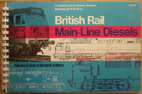
Contents: This volume presents a set of line drawings in 4mm:1ft scale (correct for 00/EM gauge model railways) of British Rail Main-Line Diesels. The 4mm scale is small, so some items such as pipe runs and cables have been left out by the R. S. Carter (artist behind the drawings). The book covers diesel classes 20; 24/1; 24/2; 25/1; 25/2; 25/3; 25/4; 26/1; 26/2; 27/1; 27/2; 27/3; 30; 31/1; 31/2; 31/3; 33/1; 33/2; 33/3; 37; 40; 'Peak' classes 44, 45/1, 45/2 and 46; 47/1; 47/2; 47/3; 50; 52 'Western'; 55 'Deltic'; 15; 17/1/2/3; 21; 22; 23; 28; 29; 35; 42 'Warship'; 43; 53 'Falcon' Trial Locomotive; 73/1; 73/2; 74
Also contains 4mm scale drawings of the 'Lion' Trial Locomotive; 'Kestrel' Trial Locomotive HS4000; DP2 Trial Locomotive; D600-4 A1A-A1A Type 4 'Warship' |
|
1991, OPC
In stock, click to buy for £42.99 Alternative online retailers to try:
Click here to access our prebuilt search for this title on Abebooks
Click here for our prebuilt search for any edition of this book on Alibris
Click here for our prebuilt search for any edition of this title on Ebay for our prebuilt search for any edition of this title on Ebay
|
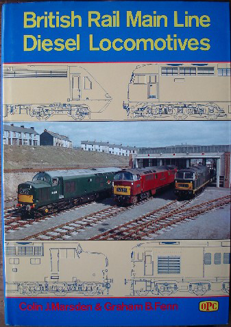
About the book: Packed full of black & white photos and facts, this book gives the reader full technical details, over 250 photographs and more than 200 4mm to 1ft scale drawings on British Rail main line diesel locomotives and their variants. It is the subject of many years of research by Colin Marsden, one of Britain's best known and most highly respected authors of modern traction. This work is backed up with the super scale drawings of Graham Fenn. The illustrations feature many official photographs not seen in print before [before this was published], in addition to photographs from well-known photographers. The book fully documents the many trials and experimental locomotives operated on Britain's main line tracks (both successfully, and unsuccessfully)
For each class below, there is information on: Former Class Codes; Number Range; Who Built it; Date of Introduction; Wheel Arrangement; Weight (operational); Height; Width; Length; Min Curve negotiable; Maximum Speed; Wheelbase; Bogie Wheelbase; Bogie Pivot Centres' Wheel Diameter; Brake Type; Sanding Equipment; Route Availability; Heating Equipment; Multiple Coupling Restriction; Brake Force; Engine Type; Engine Horsepower; Power at Rail; Tractive Effort; Cylinder Bore; Cylinder Stroke; Transmission Type; Fuel Tank Capacity; Cooling Water Capacity; Lubricating Oil Capacity; Boiler Water Capacity; Boiler Fuel Supply
Includes the Classes:
D0260 Lion
D0280 Falcon
Deltic
DP2 (Diesel Prototype 2)
GT3 (Gas Turbine 3)
HS4000 (Hawker Siddeley 4000)
10000-10001
10100
10201-10203
10800
18000
18100
Class 15 (D8200-D8243)
Class 16 (D8400-D8409)
Class 17 (D8500-D8616)
Class 20 (D8000-D8199/D8300-D8327) 20001-20228
Class 21/29 (D6100-D6157)
Class 22 (D6300-D6357)
Class 23 (D5900-D5909)
Class 24 (D5000-D5150) 24001-24150
Class 25 (D5151-D5299/D7500-D7677) 25001-25323
Class 26 (D5300-D5346) 26001-26046
Class 27 (D5347-D5415) 27001-27212
Class 28 (D5700-D5719)
Class 31 (D5500-D5699/D5800-D5862) 31001-31469
Class 33 (D6500-D6597) 33001-33212
Class 35 (D7000-D7100) Hymek
Class 37 (D6600-D6608/D6700-D6999) 37001-37906
Class 40 (D200-D399) 40001-40199
Class 41 (D600-D604)
Class 41 (252) (41001-41002) 43000-43001
Class 42 (D800-D832/D866-D870) Warships
Class 43 (D833-D865)
Class 43 (253/254) 43002-43198
Class 44 (D1-D10) 44001-44010
Class 45 (D11-D137) 45001-45077/45101-150
Class 46 (D138-D193) 46001-46056
Class 47 (D1100-D1999) 47001-47901
Class 50 (D400-D449) 50001-50050, 50149
Class 52 (D1000-D1073) Western Class
Class 55 (D9000-D9021) 55001-55022, Deltics
Class 56 56001-56135
Class 58 58001-58050
Class 59 59001-59004
Class 60 60001-60100 |
2000, OPC, hbk
1991, OPC, hbk
|
1972, Ian Allan, hbk
In stock, click to buy for £12.00, not including post and packing (£2.80)
Alternative online retailers to try:
Click here to access our prebuilt search for this title on Abebooks
Click here to access our prebuilt search for this title on Alibris
Click here  to access our prebuilt search for this title on Ebay to access our prebuilt search for this title on Ebay
|
- Building Model Locomotives [top]
Written by F. J. Roche and G. G. Templer. Edited by S. W. Stevens-Stratten
First published in 1968 in Great Britain by Ian Allan in hardback with dustjacket
Reprinted in 1972 in Great Britain by Ian Allan in hardback with dustjacket, 0711000492
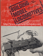
About this book/synopsis: This book comprises a long series of articles on building model locomotives that appeared in The Model Railway Constructor from 1947 to 1951. The articles covered practically every facet of the subject and applied equally to all the smaller scales used by the model railway enthusiast, although the larger scales as used by the live steam enthusiast and the model engineer were not forgotten and many of the constructional details have proved to be of use - not to mention the dimensioned drawings. These articles were, and are, regarded by many people as a standard reference work that has been unsurpassed for detail, written in a humorous and easily assimilated style. So much of what was written at that time is still valid today, and as the original issues of the magazine have long since been out of print, it is felt that there is a demand for the present volume to encompass, between two covers, all the articles including the drawings and discussions.
The articles were originally written by the late F. J. Roche, but when he fell ill in 1950, he was joined by one of his greatest critics, Colonel G. G. Templer and the series then continued as a joint effort. Stratten-Stevens has included the written discussions of both Colonel Templer and Michael Longridge as an Appendix because their ideas are felt to be invaluable and it helps to present the full story of how the finished book came about.
The book covers the whole field of building scale model locomotives, and though giving prominence to 4mm and 7mm models (OO and O gauges), the techniques described and the drawings featured are equally applicable to the larger scales, whether the motive power be by live steam or electric motor. The volume contains many unique fully-dimensioned drawings such as the range of GWR chimneys, and drawings and full descriptions of the workings of various types of valve gear. These sections and drawings are as valid and relevant today for the loco-builder as they were when they were first written or drawn.
Readers should bear in mind that the editor Stratten-Stevens has not changed the text of the original any more than necessary and as such, they should use modern alternatives to some of the materials suggested in the book - e.g. modern solders can replace the book's suggested Spirits of Salts for soldering; and readers should use modern adhesives to fix some surfaces together (since many modern adhesives were not available when the book was written)
Photographs of finished models are included. The book has been printed with a wide margin on the right hand side of each page so that the model builder can write notes on as they go along.
Contents:
Foreword
Designing the Locomotive
Requisitioning of Stores
The Tools
The Materials
The Boiler Shop
The Firebox
The Smokebox
Boiler Fittings
Cab Fittings
The Prototype
The Erecting Shop
The Frames
Springs and Axle Boxes
Wheels and Axles
Cranks and Crankpins
Bogies and Pony Trucks
Frames and Running Gear
Locomotive Kits
The GWR Bar Frame Bogie
The Bogie
Pony Trucks
The Cylinders and Valve Gear
The Valve Rod and Link
The Return Crank
Connecting and Coupling Rods
Walschaert's Valve Gear
Stephenson's Valve Gear
Joy's Valve Gear
Connecting Rods, Cross-Heads and Slide Bars
Slide Bars, Motion Plates and Brackets
Coupling Rods and Brake Gear
Brake Rigging
The Westinghouse Brake Air Pump
Preparing for the Superstructure
Soldering
Appendices:
A Criticism by Colonel G. G. Templer
-Replies from F. J. Roche
-Gauge O Locomotive Construction by Colonel G. G. Templer
-In Conclusion
Wheels and Axles by Michael Longridge
-Turning and Fitting Wheels and Axles in Gauge O
-Turning Wheel – Facing the Back and
Facing the Front
-Other Wheel Operations - drilling and tapping for crankpins, driving axles, retaining screws, quartering and force fitting driving wheels, finishing operations and balance weights
Reply: Wheel Turning by F. J. Roche
Illustrations:
1. Scaling a drawing having no scale attached - converting to a 7mm scale
-
scaling a drawing having wheelbase shown - converting to a 4mm scale
2. How to draw an ellipse - for number plates, etc.
3. Driving and bogie wheel proportions, scale 0.5"
showing bogie or trailing wheels and driving and coupled wheels.
4.
Includes scale diagrams of Henry Greenly's old standard coarse and old standard fine; also the B.R.M.S. Bureau coarse and B.R.M.S Bureau fine; also a picture of old and new wheel standards, 7mm scale "O" gauge
5. Scale interpretation showing diagrams with the incorrect and correct scale interpretation
6. Scale diagram (black and white) of Sir Henry Fowler's 4-cylinder Compound "Pacific" 1930. London, Midland and Scottish (L.M.S.) 2 h.p. cylinders 16 3/4in. x 26in.
and 2 1.p. cylinders 23 5/8in. x 26in. B.P. 240lbs/sq. in.
7. Scale diagram (black and white) of J. G. Robinson's 3-cylinder Compound Express loco. Great Central Railway, 1905. American projection
8. F. W. Webb's 3-cylinder Compound, "Jeanie Deans," "Teutonic Class,", 1890, for the H.P. cylinders 14in x 24in. L.P. cylinders 30in. x 24in. Driving wheels 7ft 1in. diameter
9. Wheel detail showing the back plate, spokes, rim and spigot
10. Bending jig showing the direction of bend, the vice and a packing piece of 1/32" plate
11. A scale diagram template for a Stirling Chimney on a scale of 3/4in.=1'
12. A scale diagram template for a Johnson's Midland Railway loco dome jig
13. Rivetting jig showing a removable guide, punch, plate, vice and steel block
14. An illustration of the various types of tools that the model locomotive builder will find useful, such as a drill, screwdrivers, side cutting nippers, a pin chuck, a Vernier caliper gauge, long-nosed pliers, a precision vice, etc
15. An illustration of a self-heating gas soldering bit, drawn at approximately half size
16. Making a Coned Boiler
17. Turning Bands on a Parallel Boiler
18. Semi-Tapered Boilers
19. Scale diagram of a frontal elevation of North Eastern Railway "Tennant", a 2-4-0 steam locomotive built 1885
20. Scale diagram of side elevation of the "Tennant" locomotive showing the lining out detail
21. The development of a coned boiler
22. Side and end elevation of a wooden firebox former
23. A tapered firebox
24. Four line diagrams showing the three stages in constructing an L.M.S. Pacific Firebox
25. An illustration of a semi-circular topped firebox
26. A scale diagram in feet and inches showing a GWR (Great Western Railway) 4-2-2, No. 3077, Princess May in side, front and rear elevation, including the tender. The rear elevation only shows the rear of the tender, and not the cab layout
27. Scale diagram of firebox clothing and moulding for LMS 5P5F locomotives
28. Scale diagram of an LMS mixed traffic 4-6-0 5P5F firebox, scale 3/4 inch to 1 foot
29. Scale diagram showing side and front elevation of a Great Eastern Railway 4-4-0 loco standard firebox. Shows an oil fuel air heater (on oil fired engines only)
30.
Scale diagram of handrail knows with proportions of full size knobs. Also shows a ship's stanchion
31. Scale diagram of an "O" gauge smokebox door
32. Scale diagram of LMS dogs as fitted to smokebox doors. Shows a G.C.R (Great Central Railway) and G.E.R (Great Eastern Railway) ring type hinge
33. Scale diagram showing the inside of a GWR King smokebox, which is exactly the same as a Castle. The LMS Princess Royal and other LMS 4-cylinder locos have the same type of fittings. Shows a side and front elevation including the blower, regulator box, superheater header, perforated zinc plate, inside cylinder, outside cylinder, and the hinged plate for access to superheater flues. The lubricating pipes are not shown as they are similar to 2 cylinder ones (shown in figure 34)
34. Figure 34 shows a scale diagram of the smokebox for 2 cylinder locmotives (simplified) which applies to G.W.R Halls, Granges, 2-6-2 tanks and the LMS 4F.
The lubricating pipes are shown as is the position for outside and inside steam pipes
35. GWR chimneys, scale diagrams - "Aberdare" class 2-6-0
36. GWR chimneys, scale diagrams - "Bulldog" 3300 class, 2251 class 0-6-0's, 5600 class 0-6-2T class, 5100 class 2-6-2T
37. GWR chimneys, scale diagrams for "Castles" 4073 - 5042, class 4-6-0
38. GWR chimneys on the "Castle" class from 5043, and locos with new boiler. Details the copper top contours as for 4073 - 5042
39. GWR chimneys, scale diagrams of "North Star" and "8' Singles of the "Iron Duke" class
40. Scale diagram of a Stanier chimney of the L. M. S. 2-6-2 tank class
41. Scale diagram of a Ross pop safety valve for LMS 2-cylinder mixed traffic locos
42. Scale diagram of an LMS top feed casing for 5P5F, 5XP, 7P and tanks (Stanier)
43. Ilustrations (line drawings) of 4 stages in turning boiler fittings - 1. Marking Off, 2. Bore and Bell Out Bottom, 3. Stage Forming Contours, 4. Stage Part Off
44. Scale diagram of chimney and dome measurements for LMS 2-cylinder mixed traffic locomotives
45. B&W illustration of how to saddle boiler fittings
46. S.V. & Whistles scale diagram, GWR
47. Scale diagrams of more GWR chimneys - this time from the "Stars" 4000 class, the "Saints" 2900 class, the "Halls" 4901 class; and the illustration on the right applies to the Grange 6800 class where the chimney is 2 3/4in. shorter. This was also fitted to the old 4-4-0 "County" class
48. GWR chimneys - scale diagrams of chimneys from the 850, 1076, 517, 1393, 2021 and 5400 class; also including an illustration on the right which applies to the Metro Tanks and Dean Singles, where the chimney was 3" shorter
49. GWR chimneys from the 4300, 2800; and separately on the right from the 4200 and 3150 class with two scale diagrams of chimneys from the "Kings" 6000 and "Counties" 1000 class below
50. Reversing gears scale diagram - a simple type of screw reverse: Lever and Screw, showing the graduated slide, screw, hand wheel, fixed nut and latch
51. A scale diagram of a GWR firedoor
52. A full page of illustrations of cab gauges: duplex gauge, main steam boiler and the steam heat pressure gauge for the coaches; also including the cab fittings plate and the proportions of the water gauge
53. A scale diagram that shows arranging splashers for sprung locos
54. Scale diagram of the frames for the GWR "City" class 4-4-0 locomotive showing the inside frame and Stephenson valve gear under slung valves
55. Sketch drawn to show how to arrive at the clearances required, in this case for an LMS 2-6-4T on a 3ft radius curve in "00" gauge scale 1/1. The 2-6-4T is one of the longest engines to be met - it is really a Pacific in reverse and is an extreme case, but the point is that the same diagram can be used for all types of engines
56. Illustration showing marking channel frames for "00" with a temporary wood or brass block
57. Illustration showing how to assemble frames for a modern locomotive with inside and outside motion plates, cut aways to clear the driving shaft from the motor, a footplate supporting angles at convenient intervals and the bogie pin; and trailing frames for "Pacifics"
58. Several diagrams (some to scale) of simple "0" gauge stretchers, 8BA CSK Screws, a round bar stretcher for "00" gauge models, a universal stretcher or dragbeam cast or built up for "O" or "I" gauges. The illustration shows the frames shaped to clear the axle bushes in the motor
59. Illustrations of springs, a spiral spring in buckle
60. Illustration of an axle box allowing for cant under action of springs
61. Illustration of a bushing device allowing the wheels on a locomotive to be removed
62. Illustration of a simple spring for 00 models with a clock spring and continuous hornstay and a simple sprung axlebox
63. Illustration of a simple hornblock and keep for sprung models
64. Illustration of a crank pin drilling jig
65. Scale diagrams of axles for "0" gauges and axles for "1" gauge (3/8" scale)
66. Scale diagrams of a section of a locomotive wheel and also showing the methods of securing wheels
67. Table of sizes of axles in the various gauges and scales
68. Scale diagram, side elevation of an L.M.S "Duchess" fitted with a corridor tender. Shows the locomotive fitted with 6' - 6" driving wheels and 280lb boiler, painted and lined in ex L.N.W.R (London and North Western Railway) style
69. Illustration showing how to make a solid double throw crankshaft
70. Illustration showing the types of crank pins (sizes to suit model)
71. Illustration of a built-up crankshaft
72. Illustration of wheel turning showing the casting as supplied to stage 4 where the operator reverses the jaws and backs off the spigot and faces the back of the wheel exposing the spokes
73. Scale diagram of the locknut type of driving wheel fixing
74. Full page illustration of how to make axle boxes, specifically a simple radial axle box for trailing wheels of G.C.R., N.B.R., G.N.R. Atlantics, Pacifics and Radial tanks
75. Scale diagram of a ten-wheeled (four-coupled) express passenger locomotive of the Great Northern Railway focusing on the frames, brake gear, axle boxes, wheels, con. rods, valances and suspension
Plates
p97. B&W photograph of a finished S gauge, 3/16in. to 1ft scale, model of an ex-LSWR Adams' radial tank built by Bernard Wright. The Southern Locomotive shown here is No. 3520. Part of a cattle truck (equally beautifully built) can be seen immediately behind the locomotive
p98. B&W photograph of a 7mm scale model of the LNER (ex-GER) class G4 0-4-4T, No. 8139 built by Ken Leeming. The only commercial parts used in the construction were the electric motor, the gearing and the transfers. This model won the Chairman's Trophy at the Model Railway Club's Competition in 1967
p99. A b&w photograph of a standard Tri-ang B12 class 4-6-0, which has been super-detailed and repainted by E. N. Bellass. A far more realistic appearance can be gained with a little work on many of the proprietary range of locomotives
p100. Top. B&W photograph of a 4mm scale (00 gauge) model of an LNER (ex-GNR) class J6 0-6-0 goods locomotive, No. 64242 with a BR cycling lion on the tender. The model was built by Frank Dyer for his Borchester layout and uses Romford TT gauge wheels and is fitted with a Romford Terrier motor
p100. Bottom. B&W photograph of a superb model of an ex-LSWR class T9 4-4-0 built by Bernard Wright for his S gauge layout
p101. Top. B&W photograph of another locomotive from the Borchester layout built by Frank Dyer - an ex-GNR class 02, 3-cylinder 2-8-0 goods locomotive, no. 63946, again with the BR cycling lion on the tender. A Zenith 004 motor has been fitted into the spacious boiler. The photo shows that the Walschaert's valve gear is fully working!
p101. Bottom. B&W photograph of Lord Rodney, a 4mm scratch-built 00 model of this lovely Southern Region Lord Nelson class locomotive, No. 863. Built by Alan Taylor
p102. Full page b&w photograph of Southern locomotive No. 479, an ex-LSWR class M7 0-4-4T entirely hand built by Bernard Wright to 3/16in. to 1ft scale
(S gauge). This is a sister locomotive to the one shown on the dustjacket
p103. Full page b&w photograph of a view of a steam depot with turntable showing the
realism that can be obtained using proprietary locomotives and plastic kits in a 4mm scale locomotive depot. Part of the realism has been obtained by suitably dirtying (now termed 'weathering') the locos to simulate the working appearances of steam locos from the 1960s
p104. Top. A b&w photograph of the side elevation of an unpainted 4mm scale model of the GWR King class 4-6-0 No. 6017, King Edward IV that has been built by Alan Taylor. Note the rivet detail on the cab and the smokebox
p104. Bottom. A b&w photograph of No. 6017
- a longer view of the other side with the tender attached
Illustrations (cont.d)
76. Scale diagrams of GWR bar frame bogie detail (actual size, 7mm scale showing front frames, rear frames, cross slides, crossbars, tie bars, bogie pins, brake hangers and centre cradle etc
77. Scale diagram of a twice full size gauge "0" model - a model G.W.R. Bar Frame Bogie (2 and 4-cylinder 4-6-0 classes). A plan of the underside and a half sectional elevation are included
78. Illustration of a G.W.R. Bar Frame Bogie (Major Sparkes System). For full description see "Model Railway Constructor" for November 1945. Shows split bearings, distance pieces, guardirons, rivet and equalisers
79. Illustration of a modern individually sprung leading bogie, which is a simplified scheme for H0 & 00 gauge (more play can be obtained on 18mm (EM) owing to wider frames
80. Illustration of a simplified sprung and equalised leading bogie, simplified for models, suitable for 4-4-0's of the Midland Region, Great Eastern Region, South Eastern and Chatham Railway, etc. It is not suitable for 4-6-0s and 4-6-2s
81. Scale diagram, plan view of a section of a bogie, showing another method of mounting bogies for 4-6-4 and 4-8-4 locos
82. Illustration of the pony truck
83. Diagrams of a rigid wheelbase (example for a 2-6-0) - shows how to find the radius of the pony truck bar
(Baldry's Rule)
84. Scale diagrams of bogie wheel proportions for a GWR engine bogie. Shows the axle and axle boxes
85. Illustration of the springing on a pony truck, "0" gauge
86. Scale diagrams of the cylinder casings for LMS 5P5F class locomotives
87. Plan views of the GWR pony truck showing side control springs, and its complete assembly. There's also a part view showing the beam, bar frame, cylinders and compensating beam
88. Illustration of the front view of a G. W. R. pony
89. Scale diagrams of a GWR 4-wheeled bogie bolster; a modern pattern strengthened bogie; with a suggested modification to the model spring
90. Scale diagram showing the arrangement of cylinder drain cocks on an L.M.S. "Stanier" design
91. Illustration of the building up of a pair of outside cylinders in "0" gauge and the outside cylinder for "00" gauge
92. Illustration of the relative positions of expansion links and return. The cranks are: "C" English and "D" American
93. Illustration of how Walschaert's Valve Gear works showing the layout and the names of the parts. The gear is shown in mid stroke. The illustration shows therefore the anchor link (or union link), combination lever, connecting rod, crankpin, drop link, expansion link, eccentric rod, girder frame, lifting arm, return crank, reverse rod, valve rod, valve spindle and the valve spindle guide
94. Illustration of the top joint of the combination lever of the Walschaert's valve gear and below it, an illustration of the LMS style of valve spindle guide, which is virtually a small crosshead mounted on a piston valve gland cover
95. Scale diagram of the arrangements of the connections of the valve rod and valve spindoles for "A" outside admission and "B" inside admission of the valve gear
96. Scale diagram of the Union Link arrangement of the Walschaert's Valve Gear for LMS 4-6-0s (sometimes known as the "Anchor Link"
97. Four illustrations showing anchor links at the top; and the two methods of making crossheads at the bottom. The top left illustration shows a simple arrangement of the anchor link for "00" gauge dispensing with the forked ends, whist the top right illustration shows an alternative arrangement of the anchor or union link showing also the slide bar and crosshead
98. Illustration of how to build up a fluted connecting rod from flat material and how to flute "00" gauge rods and small rods or valve gear for "0" gauge
99. Shows the construction and mounting of a Southern Railway type of expansion link and how to find the radius of and determine the shape of the expansion link. Also shows the construction of box-link where the valve rod is lifted or lowered from the rear of the link - LMS and LNER
100. Illustration of lifting valve rods - Southern Railway style where the valve road is raised or lowered from the front of the link; and also the LMS and LNER style of lifting the valve rod from the rear of the link
101. Illustration showing methods of fixing return cranks for "00" gauge and "1" gauge and below, two methods in "0" gauge
102.
Illustration of the suspension arrangements for the expansion link, here on the LMS type of box girder frame link suspension. On the left is an illustration of the L.N.E.R. type of expansion link bracket
103. Illustration of the return crank setting for inside admission and outside admission
104. Illustration of how to set out the return (or eccentric) crank on the main crankpin (inside admission (piston valve) cylinders)
105. Illustration of the L.N.E.R. (ex GNR) type of connecting rod big end with a separate illustration of the coupling rod joint for sprung locos
106. Scale diagram of the Walschaerts valve gear arranged for inside cylinder locomotives such as can be found on the G.W.R. "Star", "Castle" and "King" classes
107. Scale diagram of the inside gear frame of GWR 4-cylinder locomotives (actual size in 7mm scale)
108. Scale diagram of a Gresley 3-cylinder locomotive gear system
109. Scale diagram of Walschaert's valve gear
inside a GWR 4-cylinder locos. This diagram shows a section through the valve gear from the side and from above
110. Scale diagram of the Rocker gear - compensating link for 4-cylinder locomotives
111. Illustration of Stephenson's valve gear showing the weigh shaft, lifting links, fore gear eccentric rod, con. rod and back gear eccentric rod
112. Detailed scale diagram of one side of the Stephenson gear as fitted to the "Hall" and other 2 cylinder classes. It was designed originally by the late Mr. Churchward for his standard engines
113. Diagram of Stephenson's gear eccentrics showing a simple adjustable eccentric for driving outside rockers
114.
Diagram of Stephenson's gear eccentric sheaves
115. Diagram of Joy's valve gear as fitted to G.E.R. (Great Eastern Railway) 2-4-0 (Worsdell 1882)
116. Four diagrams showing the fabrication of the curved slides of Joy's valve gear
117. Scale diagram of the outside Joy Valve Gear of L.N.W.R. compound "Jeanie Deans" (Teutonic Class)
118. Diagram of a simple type of outside big end showing the outside con. rods
119. Three illustrations of various types of inside big ends (inside connecting rods). Type a) is as simplification of the marine big end; type b) is a strap type of big end and type c) is the standard strap-ended British connecting rod
120. Diagram of the inside cylinders' cross-heads and slide bars. Type a) is a single bar and crosshead used for many years on the GER and other railways; type b) shows the two-bar system with a crosshead arranged to take a forked small end; type c) is a model form of the four bar type of slide bar and crosshead used by the SR on their Schools, Nelson and Pacific classes
121. Diagram showing how to secure the slide bars using a separate back cylinder cover
122. Illustration of a slide bar clamp
123. Illustration of motion plates that allow for bogie wheel clearance. This special bracket is suitable for a multicoupled loco where the leading coupled wheel is immediately behind the slide bars
124. Illustration showing at A) little angles made up and fitted to reinforce the joints between slide bars and bracket
and at B) another method where holes are drilled and tapped in the slide bars on the centre line of the motion bracket to receive screws with large plain heads (these will need to be specially made on the lathe)
125. Illustration showing many different types of rod. Included in this illustration are two more suggestions for securing the leading end of 6- or 8-coupled rods whee clearance may be very small between the crank pin head and the motion. The figure als shows an arrangement that avoids the normal joint by placing one eye over the other on the same pin, which is stronger and simpler than the jointed rod (Webb's 8-coupled mineral engines on the LNWR were so fitted)
126. Three scale diagrams showing the brake rigging on LMSR Class 5 4-6-0s, which is a straightforward layout with central pull rods acting directly on the beams with the power cylinder under the footplate
127. Scale diagram showing the much more complex brake rigging arrangement of the LNER Class V2 Green Arrow locomotives where a double set of pull rods is used acting through compensating levers with the power for that being taken from two 24 inch vacuum cylinders located between the middle and trailing coupled axles. Their size prevents the cylinders being placed side-by-side, so they are staggered one above the other
128. Scale diagram showing the brake arrangement of the G.W.R 51XX Class 2-6-2T (and similar classes). Like figure 127, it has a double set of compensated pull rods but the pull is directly from the vacuum cylinder in the normal position. This example has been selected because it shows the hand brake connection - some such arrangement like this is necessary on all tank engines and on tenders
129.
Scale diagram showing the brake rigging of the Southern Pacifics
130. Illustration of brake rigging as employed on early LNWR locomotives. Webb, for example, used a pair of shoes between the wheels, one shoe operating on each tyre through the medium of a single hanger. Fig 130 shows how Webb disposed them on his 4-cylinder compounds where the shoes were similarly employed but with their own hanger. Fig 130 shows the arrangement of levers by which the brakes were caused to move in opposite directions when the brakes were applied
131. Shows the much preferred clasp brake where each driving wheel was provided with two brake shoes, one on either side. The underlying advantage here is that axle boxes and running gear were relieved of braking stresses. The brakes were operated by a steam cylinder disposed centrally between the coupled wheels and acting directly in opposite directions on the two inner hangers by outside pull rods provided with adjusting warwicks
132. Illustration of single and double hanger brakes. Figure 132 gives some ideas as to how the cast type of bracket can be modelled. This type of bracket can be elaborated to any extent to which the individual modeller may feel disposed
133. (wrongly labelled as 132). Illustration of single and double hanger types
134. (wrongly labelled as 133)
Illustration of how to make brake hangers
135. The brake rigging: a) shows the enlarged end of the rear pull rod with a series of holes in it; b) shows some suggestions as to how the modeller could get round the problem of the slotting of the forked ends of the pull rods (of particular problem may be the longer ends that pass over the transverse beams and extend to couple to the equalising levers; c) shows the treatment of the ends where the pull rods have been made of square wire without reducing the section between the forks (where inside brake rigging has been made)
136. This illustration shows another method of securing the brake rigging to the loco frame - in this methods, the hangers are permanently secured to the hanger brackets and the latter are provided with a small peg or spigot at the back which fits into a plain hole drilled in the frame with slightly tapered spigots
137. Scale diagram of a Westinghouse brake air pump (drawn approximately double size for 7mm scale). Shows: steam cylinder, steam chest, lubricator, pump governor, air from main reservoir, steam supply, auto drain valve, steam exhaust, air pump, air inlet, suction valves, delivery valves and air to main reservoir
138. The problem of fixing the pump to the model may present some difficulties and figure 138 offers some solutions round that. It shows the Westinghouse brake airpump fitting to firebox and boilers: a) a fixing suitable for firebox or cabside (as used on the C. R. and L.B.S.C); b) shows an alternative fitting where nuts cannot be fitted from the inside and it is therefore attached to the boiler or smokebox (SECR, LTSR); c) Shows a method where the pump can be secured to the running plate (as fitted to G.E.R Tank Engines) by means of a bracket screwed to both cylinders at the back
139. Illustration showing the erection of the locomotive's cab front and sides
140. Illustration accompanying Colonel G. G. Templer's critical analysis of F. J. Roche's book looking at three views of a locomotive at the front end to illustrate how getting the side view of your model correct can jeopardise the look of the loco at the front end where it can be demonstrated that adding in iron lamps and vacuum pipe can accentuate the discrepancy from scale
141. Illustration of the simplest chassis design possible for a model locomotive
where the correct profile is maintained along the bottom edge. This is a sketch of it as applied to a 4-6-0, again by Colonel G. G. Templer
142. Scale diagram from a reply by Michael Longridge to F. J. Roche's 'Wheels and Axles' article, showing how to construct a wheelmaking jig for the lathe so that the front of the wheel can be faced. The jig has to be in a collet, not a self-centering chuck
143. Illustration showing the process of wheel turning, e.g. where to set the round-nosed too in the lathe |
|
1977, Peco Publications, pbk
Sorry, sold out, but click image above to access a prebuilt search for this title on Amazon UK
Other Online Retailers to Try:
click here for our prebuilt search for any edition of this title on Abebooks
Click here for our prebuilt search for any edition of this book on Alibris
Click here for our prebuilt search for any edition of this title on Ebay
Don't forget to try different versions of the title, e.g. 'GWR' or 'G.W.R' on the above databases combined with the author name to see if listings exist under those titles |
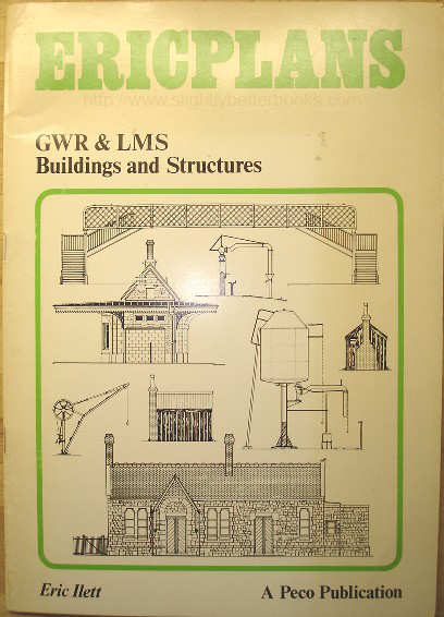
About this book: This book was produced to provide the railway modeller with detailed 4mm to 1ft scale plans on various aspects of railway buildings. It is intended to present enough examples of different types of buildings for the railway modeller to form a good idea of the character of the railway of his choice. Many of the buildings drawn can be combined together to make up typical station layouts. Methods of construction have been left to personal choice. Includes level crossings, stations, goods sheds, platelayers huts, lamp huts, water towers, footbridges, road overbridges, weighbridges, water columns and cranes, yard cranes and loading gauges (GWR); and finally there is a list of other PECO publications
While these drawings are to 4mm scale, they can be used for modelling to any size by reducing or increasing the scale
Plans included:
Level Crossing - Dunster GWR
Station - Brimscombe GWR
Station - Dunster GWR
Goods Shed - Dunster GWR
Platelayer's Hut - Andoversford GWR
Goods Shed - Leckhampton GWR
Lamp Hut - Leckhampton GWR
Platelayer's Hut - Andoversford GWR
Water Tower - Ashchurch LMS
Lamp Hut - Eckington
Platelayers Hut - Wadborough LMS
Footbridge - Ashchurch LMS
Road Overbridge - GWR
Road Overbridge - LMS (near Ripple, on the Tewkesbury branch, ex-LMS)
Weighbridge - Ripple LMS
Goods Shed - Eckington LMS
Water Column & Crane - Cheltenham GWR
Yard Crane & Loading Gauge GWR
Weighbridge - Leckhampton GWR
Signal Box - Leckhampton GWR
Signal Box - Brimscombe GWR
Platelayer's Hut - Dunster GWR
Signal Box - Cheltenham LMS
Signal Box - Dunster GWR
Signal Box - St. Mary's Crossing
Other Peco Publications |
� |
1971, Peco, pbk
2 copies in stock, 1 in good condition at £7.50 (not including p&p); and 1 in vgc at £10.50
Alternative online retailers to try:
Click here to access our prebuilt search for this title on Abebooks
Click here to access our prebuilt search for this title on Alibris
Click here to access our prebuilt search for this title on Ebay to access our prebuilt search for this title on Ebay
Click here to access our prebuilt search for this title on Biblio |
About this book: This series of books has been produced to provide the railway modeller with detailed information on various aspects of railway buildings. The series is intended to present enough examples of different types of buildings for the modeller to form a good idea of the character of the railway of his choice. Many of these buildings can be combined together to make up typical station layouts. Methods of construction have been left to individual choice; there are a number of books already available dealing with this subject. The scale of the diagrams is 4mm to 1ft
Contents:
Goods shed - Leckhampton GWR
Signal Box - Leckhampton GWR
Weighbridge - Leckhampton GWR
Lineside Huts GWR
Water Column and Crane GWR
Yard Crane & Loading Gauge GWR
Road Overbridge GWR
Station - Dunster GWR |
|
![Ilett, Eric. 'LMS Buildings & Structures [Ericplans No. 2]', published by Peco Publications and Publicity Ltd, pbk, 12pp, ISBN 0900586346. Sorry, sold out, but click image to access prebuilt search for this item on Amazon](docs/ilettericplanslmsbuildings1971pbk.jpg)
1971. Peco Publications & Publicity.
Sorry, sold out, but click image to access prebuilt search for this item on Amazon
Other Online Retailers to Try:
click here for our prebuilt search for any edition of this title on Abebooks
Click here for our prebuilt search for any edition of this book on Alibris
Click here for our prebuilt search for any edition of this title on Ebay |
About this book: In this series of books containing 4mm to 1 foot scale technical drawings, the aim has been to provide the railway modeller with detailed information on various aspects of railway buildings. The series is intended to present enough examples of different types of buildings for the modeller to form a good idea of the character of the railway of his or her choice. Many of these buildings can be combined together to make up typical station layouts. Methods of construction have been left to individual choice; there are a number of books already available dealing with this subject
Plans included :
The Cheltenham LMS signalbox, Alston Junction, on the Birmingham - Bristol line
The Ashchurch LMS footbridge on the Birmingham - Bristol line
The Ashchurch LMS Water Tower on the Birmingham - Bristol line
The Ripple LMS Weighbridge (on the closed Ashchurch - Tewkesbury Branch - Malvern Wells branch)
The Eckington LMS Goods shed on the Birmingham - Bristol line
The LMS Lineside hut, e.g. the Lamp Hut at Eckington and the Plate-Layers Hut at Wadborough
The Ripple LMS Road Overbridge |
� |
1971, Peco Publications & Publicity Ltd, pbk
Sorry, sold out, but click image to access prebuilt search for this item on Amazon
Other Online Retailers to Try:
Click here for our prebuilt search for any edition of this book on Abebooks
Click here for our prebuilt search for any edition of this book on Alibris
Click here for our prebuilt search for any edition of this title on Ebay
|
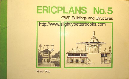
- ERICPLANS No. 5. GWR Buildings and Structures [top]
Written and drawn by Eric Ilett
First published in 1971 in Great Britain by Peco Publications and Publicity Ltd, in paperback, 12pp, ISBN 0900586354 . Glossy white card covers with green, black & white line diagrams and b&w photograph, with staple binding . Glossy white card covers with green, black & white line diagrams and b&w photograph, with staple binding
About this book/synopsis: This book contains various technical drawings, or diagrams of various Great Western Railway buildings and structures in scale 4mm:1foot. For each building and structure, different elevations are given along with details of colour, materials and features to note, like stovepipes.
Structures included are:
Brimscombe Station (on the Gloucester-Swindon line, ex-GWR)- North, East, South and West elevations. Cotswold stone, slate roof.
Brimscombe Signal Box (on the Gloucester-Swindon line) - N, E, S & W elevations. Red brick walls, slate roof
Dunster GWR Goods Shed (on the Minehead-Taunton line) - North West, South East, South West and North East elevations. Smoke-blackened red sandstone, wooden doors, slate roof
Dunster Signal Box (on the Minehead-Taunton line) - N,E,S and W elevations. Timber board walls and slate roof
Dunster Level Crossing - white gated crossing, metal hinges and fittings in black
GWR lineside huts:
Platelayer's hut, St. Mary's Crossing - wooden sleeper walls, black tarred felt roof
Platelayer's hut, Dunster - wooden sleeper walls, black corrugated iron roof
St. Mary's Crossing signal box (Gloucester-Swindon line near Brimscombe) - red brick walls, slate roof |
|
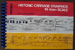
1974, Ian Allan, spiral bound, hardcover
In stock, click to buy for £27.75, not including post and packing
Other Online Retailers to Try:
Click here for our prebuilt search for any edition of this book on Abebooks
Click here for our prebuilt search for any edition of this book on Alibris
Click here for our prebuilt search for any edition of this title on Ebay
|
Contents: Published in 1969 by Ian Allan and reprinted in 1974, this is a very detailed and comprehensive book of scale drawings for the railway modeller. The brief for the authors of this book was simple. They were asked to assemble 100 pages of drawings to be divided equally between LMS (London Midland Scottish Railway) and LNER (London and North Eastern Railway) types with a balance to be struck between pre-and post-grouping designs. They were also asked to provide sufficient ancillary details such that modellers could produce accurate basic models. Whilst most drawings in the book are the work of David Jenkinson and Nick Campling, there are those that come from other draughtsmen and therefore there are stylistic differences between those produced by the different sources. The book credits the artist of each carriage drawing for the reader's information.
With the exception of livery, which is summarised after the introduction, basic prototype information is given on insert pages between the drawings to which they refer. This has enabled less encroachment to be made on the drawing area. The reader should note that occasionally railway companies made alterations to carriages without adjusting the works drawings and though sometimes these can be corrected from pictures, this isn't always the case because carriages have never been photographed quite so extensively as locomotives. Further, in some cases, the original works drawings themselves are deficient in certain details necessitating reference to pictures (if available) or involving assumptions that standard and known practices were followed in the particular design concerned.
Contents:
Coach Livery: LMS Standard Liveries; Pre-Group liveries (LMS Constituents); LNER standard liveries; Pre-Group liveries (LNER Constituents)
LMS Coach Numbering
LNER Coach Numbering
LMS Drawings
LMS standard underframes/bogies
LMS standard end elevations
LMS standard corridor brake third: 1926-30
LMS standard corridor stock: 1924-29
LMS standard corridor stock: 1927/30
LMS standard vestibule stock: 1923-28
LMS first class corridor vestibule car: 1928
LMS luxury stock: 1928-29
LMS standard corridor brake composite: 1930
LMS standard corridor stock: 1929-30
LMS standard gangwayed stock: 1930-32
LMS Stanier corridor stock - I
LMS Stanier corridor stock - II
LMS Stanier corridor stock - III
LMS Stanier corridor stock - IV
LMS Stanier vestibule stock - I
LMS Stanier vestibule stock - II
LMS Stanier articulated excursion stock
LMS standard first class sleeping car: 1925-30
LMS standard third class sleeping car: 1928-31
LMS standard composite sleeping car: 1930-31
LMS standard first class sleeping car: 1935
LMS standard third class sleeping car: 1933
LMS standard first class kitchen/dining car: 1930
LMS standard third class kitchen/dining car: 1933-37
LMS standard 57ft non-corridor stock: 1925-30
LMS standard 57ft non-corridor stock: 1924-29
LMS standard 57ft non-corridor lavatory stock: 1927-30
LMS standard 57ft non-corridor stock: 1930 onwards
LMS standard 50ft full brakes
LNWR arc roof 50ft stock
LNWR low elliptical roof 50ft lavatory stock
LNWR/WCJS corridor stock
WCJS 65ft 6in corridor stock
WCJS 65ft 6in clerestory stock
Midland Clayton six-wheel stock
Midland 48ft clerestory express lavatory stock
Midland 48ft Bain suburban stock
Midland 54ft Bain clerestory corridor stock
Midland 59ft Bain dining carriage
Lancashire & Yorkshire stock - I
Lancashire & Yorkshire stock - II
Lancashire & Yorkshire stock - III
North Staffordshire bogie carriages
Furness Railway and Maryport & Carlisle stock
Glasgow & South Western stock
Glasgow & South Western and Caledonia 12-wheel stock
Caledonian 57ft non-corridor stock
Caledonian corridor composite; Highland brake third
Highland Stock
LNER drawings
LNER Gresley 61ft 6in corridor brake composite: 1930
LNER Gresley 61ft 6in corridor three compartment brake third: 1924
LNER Gresley 61ft 6in corridor four and five compartment brake third: 1924-39
LNER Gresley 61ft 6in corridor composite: 1928-40
LNER Gresley 61ft 6in corridor full first, third and brake composite: 1925-43
LNER Gresley 61ft 6in buffet car: 1933
LNER Gresley 61ft 6in corridor full brakes - three varieties: 1924-38
LNER Gresley 61ft 6in corridor end vestibule four compartment brake third
LNER Gresley 61ft 6in corridor end vestibule full third and composite: 1934
LNER Gresley corridor end vestibule locker composite and full first
LNER Gresley 61ft 6in open third and semi-open first
LNER Gresley 61ft 6in open first and open-brake third
LNER Gresley 61ft 6in first and third sleeping cars
LNER Gresley 61ft 6in restaurant car: 1931
LNER Gresley 52ft 6in corridor full first, full third and composite: 1927-38
LNER Gresley 52ft 6in corridor brake third and open third
LNER Gresley 52ft 6in corridor full brake and open brake third
LNER Gresley steel panelled stock - I
LNER Gresley steel panelled stock-II
LNER Gresley tourist twin open third and open brake third
LNER Gresley tourist buffer car and plan of Clayton railcar
LNER Clayton railcar and trailer
LNER Gresley triplet restaurant car: 1924
LNER Gresley triplet restaurant car: 1924
LNER Gresley twin sleeping car first: 1926
LNER Gresley 51ft 1.5in non-gangwayed semi corridor lavatory composite: 1924
LNER Gresley 51ft 1.5in non-gangwayed
four compartment brake third, including Auto coach rebuilding
LNER Gresley 51ft 1.5in non-gangwayed twin third/brake third; brake third/lavatory composite; third/third
LNER Gresley 51ft 1.5in non-gangwayed full first and full brake
LNER Gresley TPO van
LNER Thompson corridor three compartment brake third, full first, full third, brake composite, and full brake (Type I): 1946
LNER Thompson corridor composite and full brake (Type II): 1945-6
LNER Thompson non-gangwayed brake composite and end views
LNER Thompson non-gangwayed four and five compartment brake third; 54ft open lavatory third
LNER Thompson non-gangwayed semi-corridor lavatory composite, first and third
GN triplet and six-wheel full brake
GN clerestory corridor locked third
GC Barnum open third, open brake third and matchboard brake composite
GC matchboard stock - three types
GE corridor brake third and composite
GE non-gangwayed lavatory composite and corridor third
NER bow ended corridor third and full brake
NER non-gangwayed brake third, third and lavatory composite
H&B non-gangwayed lavatory stock
NBR corridor stock - brake third and composite
NBR non-corridor stock - first, third
composite brake third
GNS corridor composite and non-corridor third
LNER End views
Pre-grouping end views
Detail drawings, livery, etc
|
|
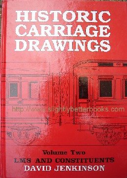
1998, The Pendragon Partnership, hbk
In stock, click to buy for £23.85, not including p&p
Other Online Retailers to Try:
Click here for our prebuilt search for any edition of this title on Abebooks
Click here for our prebuilt search for any edition of this title on Ebay
Click here for our prebuilt search for this title on Alibris
|
About this book/synopsis: This book gives the reader a new and updated view of a large proportion of the original LMS/LNER material from the 1968-1969 historic carriage drawings book (by David Jenkinson & Nick Campling) along with a few alterations and improvements including extra prototype data and modest photographic coverage (not present at all in the 1968 publication). There are also a few extra drawings. The presentation has been reorganised to offer a 'wipe clean' cover with page layouts that open away from the reader to help modellers view them easily whilst working from them on their workbench. The aim of the book is not to allow full-size replicas to be made, but to give accurate data at the sort of level that will allow an appreciation of the major characteristics of a large variety of historical carriages; and it will allow close replicas to be created by modellers working within 2mm-10mm/1ft scales
Although most drawings in the volume are prepared from original sources (i.e. works drawings and, or actual vehicles), it has to be pointed out that many variations occurred and a few of them are unrecorded.
In general the book structure is the same as in Volume One (that is drawings presented opposite the data in landscape form to make bench use easier). Extra background detail has been added and the LMS livery section has been expanded in the light of more recent research.
The extra research has meant that the basic pre-LMS livery summary in book one has not been reproduced; rather appropriate, brief pre-group livery details have been added on the text pages following each of the LMS constituent companies.
Also included in this volume are drawings and prototype information accompanying them from other draughtspersons. These are:
Gordon Heywood (late); Ralph E. Lacy (late); John B. Hinchliffe (late); Julie Hinchliffe; Barry C. Lane; Ken Morgan; Mike Peascod; Iain R. Smith (late); Peter Tatlow; Graham Warburton; Arthur Whitehead; Alistair Wright
Additional Scottish prototype information was supplied by the late Duncan Barton; along with Dr. Niall Ferguson and Jim Smellie
Contents:
Editor's General Introduction
The LMS and its Constituents
LMS Carriage Numbering and Liveries
LMS Insignia and Panel detail
LMS Standard Underframes and Bogies
LMS Standard Carriage Ends
LMS Standard Period I Corridor Brake Third
LMS Standard Period I Corridor Stock
LMS Standard Period I Corridor Stock (later style)
LMS Standard Period I Vestibule Stock
LMS Standard Period I/II Luxury Semi-Open First
LMS Standard Period II Corridor Brake Composite
LMS Standard Period II Corridor Stock
LMS Standard Period II Gangwayed Stock
LMS Standard Period I/II 'All Steel' Stock
LMS Standard Period III Corridor Stock-I
LMS Standard Period III Corridor Stock-II
LMS Standard Period III Corridor Stock-III
LMS Standard Period III Corridor Stock-IV
LMS Standard Period III Corridor Stock-V
LMS Standard Period III Vestibule Stock-I
LMS Standard Period III Vestibule Stock-II
LMS Standard Period III Articulated Stock
LMS Standard Period I First Class Sleeping Car
LMS Standard Period I Third Class Sleeping Car
LMS Standard Period II Composite Sleeping Car
LMS Standard Period III First Class Sleeping Car
LMS Standard Period III Third Class Sleeping Car
LMS Standard Period II Dining Cars
LMS Standard Period III Third Class Dining Car
LMS Standard Period I 57ft Non-Corridor Stock
LMS Standard Period I 54ft and 51ft Non-Corridor Stock
LMS Standard Non-Corridor Lavatory Stock
LMS Standard Period II/III 57ft Non-Corridor Stock
LMS Standard 50ft Full Brakes/50ft Underframe
LNWR 50ft Arc Roof Non-Corridor Stock
LNWR 50ft Cove Roof Non-Corridor Lavatory Stock
LNWR 50ft Arc Roof Corridor Stock
LNWR 57ft Cove Roof Corridor Stock
LNWR 57ft Elliptical Roof Corridor Stock
LNWR/WCJS Clerestory Sleeping & Dining Cars
LNWR Clerestory Composite Dining Car
WCJS Special 12-wheel '2pm' Corridor Stock
Midland Railway Six-wheel stock
Midland Railway 48ft Lavatory Clerestory Stock
Midland Railway 48ft Low Roof Bain Suburban Stock
Midland/MSJS Bain Corridor Clerestory Stock
Midland Railway 59ft First Class Clerestory Dining Car
LYR Attock Stock
LYR Attock Stock Developments
LYR Arc Roof Open Stock
LYR Elliptical Roof General Service Stock
LYR Elliptical Roof Open Stock/Dining Car
North Staffordshire Railway Bogie Stock
Maryport & Carlisle/Furness Railway Stock
Furness Railway Bogie Stock
Caledonian Railway 'Grampian' Corridor Stock
Caledonian Rarilway 57ft Non-Corridor Stock
Caledonian Railway Corridor Stock
G&SWR 43ft General Service Non-Corridor Stock
G&SWR Gangwayed Stock
Highland Railway Bogie Non-Corridor Stock
Highland Railway Bogie Corridor Stock
Colour Panels, Bibliography
|
Books on Railway Carriages:
Books on rolling stock:
|
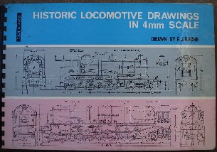
Undated, Ian Allan
In stock, click to buy!
Other Online Retailers to Try:
Click here for our prebuilt search for any edition of this title on Abebooks
Click here for our prebuilt search for any edition of this title on Ebay
Click here for our prebuilt search for this title on Alibris
|
Contents: The book contains the Roche drawings, all originally produced over a period between 1948 and 1952. They were always available individually, but this edition combines them in book form in a format that allows each to be laid flat and at an economic price per drawing. They were produced by Roche especially for model builders from British Railways original drawings. Allowances must be made for overscale wheel flanges and gauge/scale discrepancies that arise even where B.R.M.S.B dimensions are adopted.
The Roche drawings were available in both 4mm and 7mm-1ft scales, but only the 4mm drawings were found to be suitable for production in book form. The drawings here include a representative collection of locomotives from all four group companies. May detail variations are included but, as Mr Roche noted on the drawings, neither the complete drawing or details should be taken as representing all engines in a class. Tenders are drawn separately and are grouped after each company's locomotives with a key reference showing to which locomotives they are paired. Also included at the end of each group are drawings, to enlarged scale of locomotive fittings.
Since the drawings were originally prepared, alterations in class details and numbering had occurred, particularly in the power classification of L.M.S locomotives and in the adoption of the British Railways numbering system. Some drawings are therefore not up to date as of the time of publication (c. 1971) and remain therefore out-of-date. Nor have some of the minor errors on the originals been corrected. A new drawing of the tender coupled to the L.M.S Coronation 4-6-2s was included instead of the smaller tender originally shown for these locomotives.
Engines Included, split by pre-BR grouping
|
| L.M.S |
L.N.E.R |
G.W.R |
S.R |
| Stanier Class 5 4-6-0 |
Class B1 4-6-0 |
"King" Class 4-6-0 |
"Battle of Britain" Class 4-6-2 (in original condition) |
| Class 7P 4-6-2 No.6256 |
Class A3 4-6-2 |
"Castle" Class 4-6-0 |
"King Arthur" Class 4-6-0 |
| 0-6-6-0 (Co-Co) diesel-electric locomotive No. 1000 |
Class L1 2-6-4T |
"Modified Hall" Class 4-6-0 |
"Lord Nelson" Class 4-6-0 |
| Ivatt Class 2 2-6-0 |
Class N7 0-6-2T |
"Star" Class 4-6-0 |
Class M7 0-4-4T |
| Class 7P 4-6-2 (non-streamlined) |
Class N2 0-6-2T |
5100 Class 2-6-2T |
Adams 4-4-2T |
| Ivatt Class 2 2-6-2T |
Class J39 0-6-0 |
4500 Class 2-6-2T |
"Schools" 4-4-0 |
| Class 8F 2-8-0 |
Class J69 0-6-0T |
9400 Class 0-6-0PT |
Class Q 0-6-0 |
| Class 3F 0-6-0T |
Class A2 4-6-2 (Peppercorn) |
5700 Class 0-6-0PT |
Classes U and U1 2-6-0 |
| "Royal Scot" Class 4-6-0 (rebuilt) |
Class A1 4-6-2 No.113 |
1400 Class 0-4-2T |
Class T1 0-4-4T |
| 0-6-0 diesel-electric shunter No. 7059 |
Class A1 4-6-2 (Peppercorn) |
4700 Class 2-8-0 |
"Remembrance" Class 4-6-0 |
| Fowler Class 2F 0-6-0T (dock shunter) |
Class B12 4-6-0 (Belpaire Firebox) |
4-4-2 No. 40 North Star |
Classes E and E1 4-4-0 |
| Stanier 3-cylinder Class 4P 2-6-4T |
G.C. "Immingham" Class 4-6-0 |
4-4-2 De Glehn Compound No. 104 Alliance |
"Merchant Navy" Class 4-6-2 (in original condition) |
| Ivatt Class 4 2-6-0 |
Thompson 4,200 gallon tender |
4-2-2 Dean Single No. 3009 Flying Dutchman |
Bulleid 4,500 gallon tender |
| Class 4P 4-4-0 Compound (Fowler) |
5,000 gallon corridor tender |
"County" Class 4-6-0 |
5,000 gallon "King Arthur" tender |
| Class 4P 4-4-0 Compound (Deeley) |
Thompson 5,000 gallon tender |
"Saint" Class 4-6-0 |
5,000 gallon "Lord Nelson" tender |
| Class 2P 4-4-0 (Fowler) |
Holden 3,450 and 3,500 gallon tender |
Dean 2-4-0T No.1 |
Maunsell 4,000 gallon tender |
| Class 4F 0-6-0 |
Robinson 4,000 gallon tender |
"Manor" Class 4-6-0 |
Drummond 4,000 gallon tender |
| "Royal Scot" Class 4-6-0 (unrebuilt) |
L.N.E.R. chimneys, domes, safety valves and whistles |
Rebuilt "Armstrong" Class 4-4-0 |
Maunsell 3,500 gallon tender |
| "Jubilee" Class 4-6-0 (rebuilt) |
L.N.E.R details and cab fittings |
5600 Class 0-6-2T |
4,000 gallon "Schools" tender |
| L.T.S 4-4-2T No. 39 (L.M.S No. 2137) |
|
Churchward 4-4-2T No. 4600 |
Wainwright 3,450 gallon tender |
| Class 2F 0-6-2T (ex-L.N.W.R) |
|
A1A-A1A Gas Turbine Locomotive No.18000 |
S.R. chimneys and domes |
| Ivatt 3,000 gallon tender |
|
Collett 4,000 gallon tender |
S.R. details and cab fittings |
| Stanier 4,000 gallon tender |
|
3,500 gallon tender |
|
| Fowler 3,500 gallon tender |
|
Dean 3,000 gallon tender |
|
| Ivatt 3,500 gallon tender |
|
Hawksworth straight-sided 4,000 gallon tender |
|
| Deeley 3,500 gallon tender |
|
3,000 gallon tender |
|
| Stanier 4,000 gallon tender (Class 7P 4-6-2) |
|
G.W.R. chimneys, domes, safety valves and whistles |
|
| L.M.S details |
|
G.W.R. details and cab fittings |
|
| L.M.S. chimneys and domes |
|
|
|
| L.M.S. safety valves and whistles |
|
|
|
| L.M.S cab fittings |
|
|
|
| |
|
|
|
|
1971, Ian Allan
1964, Ian Allan
If you can't find the price/book you want on Amazon, try this prebuilt search on Abebooks:
Click here to run search.
|
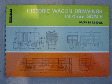
1978, Ian Allan
Sorry, sold out, but click image to access prebuilt search for this title on Amazon
Alternative Online Retailers to try:
Click here for our prebuilt search for any edition of this title on Abebooks
Click here for our prebuilt search for any edition of this title on Alibris
Click here for our prebuilt search for any edition of this title on Ebay
|
Contents: A good drawing of the prototype is an essential aid in almost every form of model building, but particularly in railway modelling, where locomotives and rolling stock are constructed to a particular scale within critical limits. For many years, modellers have used the Roche drawings because they are acknowledged to be the best of their species, with particularly fine detail captured. The drawings have been prepared especially for model builders from British Railways original drawings, but allowances must be made for overscale wheel flanges and gauge-scale discrepancies which arise, even where B.R.M.S.B dimensions are adopted.
Please note that the Roche drawings have always been available individually quite apart from the book form. The individual drawings were originally available in both 4mm and 7mm-1ft scales, however the drawings in book form are available only in 4mm.
This book assembles drawings, two types to a page, from the four group companies including examples from pre-grouping railways. The selection is representative. The standard RCH private owner open wagons could be found all over the British railway network in pre-nationalisation days and are included, but it must be noted that the many liveries they carried are not shown because they are too numerous and complex. But if the reader is interested, they did appear from time to time in 'Model Railway Constructor'
Roche does describe a number of detail variations, but neither the complete drawing or details should be taken as representative of the entire type. Nearly all the wagons and vans included in this worthy volume survived into the ownership of British Railways. The introduction to the book notes that it is unfortunate in the light of this that it has not been possible to revise the drawings to include any BR modifications or details of later BR livery.
Wagons included:
Private owner 10 or 12ton open wagon steel underframe
Private owner 10 or 12ton open wagon wood underframe
LMS (LNW) 10ton open wagon
GW "Mica A" insulated goods van
GW "Mica B" insulated goods van
SR 10ton open wagon
SR 12ton open wagon
LMS 8ton dropside open wagon
LMS 12ton dropside open wagon
LNE 12ton box van
LNE (H&B) 6ton refrigerator van
LMS 12 ton box van
LMS (Midland) 8ton outside-framed box van
SR 12ton shock absorbing open wagon
GW 13ton open wagon
SR 12ton shock-absorbing ventilated van
GW 10 ton ventilated banana van
GW 20ton steel mineral wagon
GW 12ton open wagon
GW 20ton steel coal wagon (4 door)
GW "Mink A" 10ton all-metal covered van
GW 10ton outside-framed fruit van
GW 8ton cattle van
Shell-Mex Fuel oil tank wagon wood underframe
Anglo Persian Oil Co. Twin tank fuel oil wagon steel underframe
LMS Large cattle van
LMS (LNW) 7ton box van
LMS Container Wagon
LMS 6-wheel road vehicle carrier
LNE Steel hopper wagon
LNE Steel plate wagon
LMS 6-wheel overload construction wire wagon
LMS (LNW) 4-wheel carriage truck
SR 40ton ballast bogie hopper wagon
SR (LBSC) 10ton box van
GW "Damo A" motor car van
GW "Damo B" motor car van
GW "Mink D" 10ton fruit van
GW "Paco C" horse box
LMS (L&Y) 20ton loco coal wagon
LMS (NS) 15ton loco coal wagon
LMS (LNW) 6-wheel breakdown train riding van
LMS (CR) 50ton iron-ore bogie wagon
LNE (GC) 15ton bogie fish van
LNE (CLC) Horse box
LMS (Midland) Weighing machine adjustment van
LMS (Midland) 8ton dropside wagon
LMS (Midland) 8ton box van
LMS (L&Y) 12ton mineral wagon
LNE (NE) 12ton covered van
LNE (NE) 15ton covered van
LNE 50ton sulphate bogie wagon
LNE (NE) 25ton covered bogie van
LNE (NE) "Flatrol M" bogie well wagon
LNE (NE) Bogie bolster wagon
GW "Mink F" all-metal bogie covered wagon
GW All-metal bogie loco coal wagon
GW 20ton brake van
GW
Shunters truck
LMS (CR) 15ton brake van
LMS (L&Y) 20 ton brake van
LNE 20ton brake van
LNE (GN) 8 ton well glass wagon
SR 25ton brake van
SR (LSW) 20ton brake van
LMS 12ton vacuum-fitted open wagon
LMS 12ton standard mineral open wagon
|
1970, Ian Allan, hbk
1965, Ian Allan, hbk
Other titles you may find of interest:
|
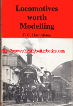
1977, Model and Allied Publications, hbk
In stock, click to buy for £20.00, not including post and packing
Alternative online retailers to try:
Click here to access our prebuilt search for this title on Abebooks
Or click here to access our prebuilt search for this title on Alibris
Or click here to access our prebuilt search for this title on Ebay
|
About this book/synopsis: The enthusiastic builder of miniature locomotives frequently experiences much difficulty when he or she desires to build a replica of some engine which took his fancy in boyhood days; the difficulty is, usually, where to look for accurate and authentic drawings and dimensions of the chosen engine. To meet this need, the author began, some years ago, to prepare drawings and collect particulars of many locomotives of the pre-grouping era. For the uninitiated, pre-grouping means the period before the hundreds of privately owned railway lines were grouped into what are called the 'Big Four' - the GWR, LNER, LMS and Southern Railway. The Railways Act 1921 took effect on the 1st January 1923.
This book contains a selection of these drawings and descriptions; it should meet with the immediate approval of many-model makers as well as of large numbers of readers who are keenly interested in the history of British Locomotives. Readers should note that since the book was originally published in 1949, some of the locomotives were produced in kit form. Scratch-builders and kit builders will find this book invaluable.
Contents:
1. Heroes of the Paris Exhibition of 1889
2. The Later Midland Railway Singles
3. A G. W. R. Contest (Great Western Railway)
4. The L. N. W. R Precedents and Their Pilots
5. Three and Four Cylinder Compounds of the L. N. W. R.
6. A Noble Descendant of the Crewe Tradition
7. Goods Engines With A Common Ancestry
8. Midland Railway No. 1447
9. L. B. & S. C. Railway "Vulcan" Goods Engines
10. A Splendid Gateshead Giant
11. Stratford Beauties
12. Engines Built In London
13. London and South Western Railway, No. 591
14. L. C. D. Railway, No. 145
15. The Famous Great Northern Number One
16. M. S. & L. Railway, No. 694
17. Two Charming Little Shunting Engines
Drawings; Figures and Illustrations by page
Heroes of the Paris Exhibition
p2. A sketch of the first 4-2-2 inside cylinder locomotive, No. 2001, side elevation. With 8ft wheels, these G.W.R. rebuilds took a big share in the express work of 1872. No dimensions given
p3. The famous Caledonian No. 123, the first single-wheeler to be fitted with air sand-blast, to prevent slipping. Dimensions of wheelbase given in feet and inches. Side elevation
p4. Scale side elevation drawing of the first of the Johnson singles, No. 25; - Nos. 25-32, 37 and 1854-62, were the eighteen of the 7ft. 4 in. class built in 1887-89
p6. Side elevation and half-front elevation (with dimensions) of No. 1853, an exhibition engine with much the same dimensions as No. 25, but cylinders and the 7ft. 6 in. driving wheels were larger. Later on, rear sandboxes wer fitted. Standard Midland Railway locomotive smokebox, cab and buffer beam are features of the front elevation of No. 1853.
p7. Scale diagram of a standard Midland Railway chimney casting and double smokebox with circular tub-plate
p8. The Midland lamps were engine-red with black edging and fine yellow line. Note the brass lens ring and polished handle. Dimensions are given.
p8. Tender of No. 1863 and 115. Many are still in use today. Shows dimensions of the wheelbase and from buffer beam (the end that would be in contact with the locomotive) to the start of the wheelbase
p10. Scale side elevation drawing of No. 240 - a noble representative of English design at the Paris Exhibition of 1889
p12. Front elevation scale drawing of "Onward", a South Eastern Railway exhibit - a handsome black-painted engine, No. 240. "Onward" is the motto from the South
Eastern Railway's Coat of Arms. No. 240 was designed by James Stirling, who was at that time in charge of Ashford Works. A finely designed wing plate was a feature of "Onward". No. 240 won a gold medal at the exhibition after running some exciting competitive trials
p13. Front elevation drawing (scale) of G. N. R. (Great Northern Railway) No. 1.
so that the reader can compare it to the S. E. R. engine (there are strong resemblances)
p13. Bottom picture: Scale side elevation drawing of Onward's tender - with deep frames and compensating brake pull-rods
p14. Top (scale) drawing - "Right-away!" for Folkestone! Headboard and lamp displayed on this route
p14. Table of useful dimensions of "Onward" 240 from Bufferbeam to centre of bogie pin to Trailing Overhang
p15. Scale drawing of the jointed intermediate valve spindle of the link motion of No. 240 - an old-fashioned arrangement. The spindles were slung at the outer ends from vertical swing links
p16. Side elevation scale drawing of No. 189, Edward Blount; an engine reputed to have been easy to handle and attractive too. Edward Blount was a Wiliam Stroudley engine and a photograph of the locomotive can be found on p106 of Stroudley Locomotives: A PIctorial History. There is a page all about William Stroudley and his engines
p16. Bottom drawing - side elevation scale drawing of the tender for No. 189, which weighed only 15 tons, 7 cwt when empty
p17. Scale diagram, front elevation, of No. 189, Edward Blount, highlighted by the author as an engine many would describe as '"The loveliest engine ever"'
p18. The cab layout of Edward Blount to scale described as "wonderfully neat." The interior was yellow, with white roof, firebox by stays black, and panel above the door tray olive green
p19. Scale diagram of the balanced cranks of No. 189
p20. Scale diagram of No. 189's chimney, described by the author as the "perfect chimney!"
p21.
Top scale diagram - No. 189's cylinder lubricator which Billinton also put on his first twenty goods engines
p21. Bottom scale diagram - the Stroudley safety valve, which was more elaborate than the Midland Railway version. However Billinton used it on all his L.B.&S.C.R goods engines when he returned to Brighton
p22. Top scale diagram - The Stroudley whistle was a nice piece of brass-turning, and its B flat note had a musical quality as agreeable to the ear as its outline was to the eye
p22. Bottom scale diagram - the Stroudley whistle handle was a neat job and felt pleasant to the driver's hand
p23. Scale diagram of the standard Stroudley buffer showing the two printed bands across the claret socket
p24. Table of useful dimensions of Edward Blount
2. The Later Midland Railway Singles
p26. Full page scale side elevation drawing of No. 115, a classic Midland Railway example
p27. Drawing of The Midland signal-lamps which gave a splendid splash of deep green for "right away" with their large reflectors
p28. Full page scale side elevation drawing of No. 2601 Princess of Wales - the M.Ry. exhibit at Paris, 1900
p29. Top. Front elevation scale drawing of No. 2601, showing the same widths as those of No. 115
p29. Bottom. Side elevation scale drawing of a Midland Railway bogie-tender
p30. Scale plan of the crank axle and outside axlebox of both Nos. 115 and 2601
p31. Table of dimensions of the 115 Class and the "Princess of Wales" Class
3. A G.W.R Contest
p33.
Scale side elevation of No. 3021, the first of the famous G.W.R 4-2-2 express engines, often proclaimed as the most handsome of all locomotives
p34. Scale diagram of the crank axle of the 7ft 8.5in singles of the GWR
p35. Full page scale diagram of the G.W.R. shield in cast-iron, which was a grand ornament displayed on the splasher of this locomotive
p36. Scale diagram, front elevation of No. 8 "Gooch" showing the enormous size of the splendid polished brass dome
p37. The 3,000 gallon tender of "Gooch
p38. Top - scale drawing of the pride of the Great Exhibition of 1851 and Gooch's masterpiece "Lord of the Isles"
p38. Bottom. Scale drawing of Three generations of chimney: Stephenson's "North Star"; Gooch's "Iron Duke" and Stroudley's "Belgravia".
Table of useful dimensions
4. The L.N.W Railway "Precedents" and Their Pilots
p41. Full page scale side elevation drawing of No. 790 entitled "Dear Old "Precedents," how lovely they were! "Hardwick," "Charles Dickens,""Eamont" and "Vulcan" were perhaps the most famous of the gallant 166 engines
p42. Front elevation scale drawing of a standard "Precedent" built between 1874-1894. 166 were built in total. The diagram shows the smokebox hopper
p43. 2 diagrams - 1) of the polished brass regulator-valve lubricator mounted at the base of the chimney; and 2) - a scale diagram of an example of "Hardwicke's" charming headlamps - the author states that you could actually see the flame through the clear glass in the lamp. The double-cone reflector was a nice example of the skill of the coppersmith
p44. Full page of scale diagrams - the old coupling rods; the author has even marked in where they were black (with dirt) and he states that the end was polished. The newer fluted rods were completely bright. He has also drawn to scale the layout of the "Precedents'" straight-link valve-gear with a curious feature of a 1 inch offset. This was used by Stirling in his "eight-footers"
p45. A scale diagram of a reversing wheel with an 'excellent "feel" about it'
p46. Illustration of how No. 2175 "Precedent" looked when new in December 1874. No dimensions are given
p47. Scale drawing of blower-valve, which was placed on the left-hand side smokebox
p48, top left. Scale diagram of the Webb chimney - the cap had the unusual refinement of an undercut moulding with a radius of 1 15/16 inches
p48, top right. Scale diagram of the Ramsbottom door as fitted to the "Precedent" Class
p48, bottom.
Scale diagram of a standard sand-box lid, and top lamp socket for the smokebox
p50. Scale diagram of the regulator handle
p51, top. Scale diagram of a standard L.N.W.R connecting-rod with traditional "small-end"
p51, bottom.
Scale diagram of a standard L.N.W.R cross-head, and big-end of the connecting-rod as fitted to the rebuilt "Stephenson"
p52. Scale diagram, side elevation of the standard 1,800 gallon L.N.W.R tender
p53. Illustration of "Precedent" Class No. 1045, "Whitworth", a smaller six-foot version of the "Precedents", which appeared in September, 1889.
No dimensions are given
p55.
Front and side elevation scale diagrams of No. 279, "Stephenson", a little "single-wheeler" with (as the author describes it) "all the best characteristics of the L.N.W.R."
p56. Table of the dimensions of No. 279, "Stephenson" when last rebuilt
5. Three- and Four-Cylinder Compounds of the L.N.W.R.
p58. Scale diagram, side elevation of No. 66, "Experiment," the first of the Webb three-cylinder compounds
p60. Scale diagram, side elevaion of No. 1309, "Adriatic", as she ran her record trip to Crewe in the 1895 Race to the North
p61. Table of useful dimensions of the Webb Compounds - looking at No. 66, "Experiment" vs. the "Jeanie Deans" class, engines with big 7ft 1 in. driving wheels. They proved an instant success and took their full share of express duties. with excellent results. There is also a table listing the engines from 1301 "Teutonic" to 1312 "Gaelic" and when they were built
p62. Scale diagram, front elevation, of "Adriatic" revealing the enormous L.P. cylinder placed inbetween the frames
p63. Scale diagram of the layout of the high-pressure cylinder Joy valve-gear on "Adriatic"
p64. Side elevation illustration (no dimensions) of No. 1038, a Deeley engine - these were the most successful compounds in regular use in this country
p65. Front elevation scale diagram showing a compound with the H.P. cylinder in the middle (the reverse of the Webb system).
p66. Table listing all the engines in the "Alfred the Great" Class
p67. Scale side elevation diagram of No 1955, "Hannibal", the last of the Webb compounds
p68. Front elevation scale diagram of a four-coupled compound, which appeared on the L.N.W.R in 1899 - Webb had abandoned the single wheeler type and built 80 engines of the new four-coupled type which all had two H.P. and two L.P. cylinders (the latter placed inside). The scale diagram on p68 shows the two low pressure cylinders inside the main frames
p69. Scale diagram, side elevation, showing the 2,500 gallon tender of "Hannibal" with traditional L.N.W. wooden framing
6. A Noble Descendant of the Crewe Tradition: Lancashire & Yorkshire Railway No. 1093
p72. Scale diagram, side elevation of Aspinall's No. 1093
p73. Top. Scale diagram of No. 1093, front elevation
p73. Bottom - scale diagram of Joy's valve-gear as fitted to Lancashire and Yorkshire Railway No. 1093
p74. Top. Scale diagram of the screw reversing gear on No. 1093
p74. Bottom. Scale diagram of Ramsbottom's screw reversing gear as fitted to D.X. class
p75. Scale diagram, side elevation, of No. 355, the first Ramsbottom D.X. goods engine, September, 1858
p75. Table of the key dimensions of the D.X. goods engine from length of buffers to width over coping on the tender
p76. Full page front elevation scale diagram of No. 399, a D. X. goods engine
p77. Side elevation of the L&Y tender attached to No. 1093
7. Goods Engines With A Common Ancestry: The L.B.S.C.R. "C" Goods Engines
Focuses on Stroudley's 0-6-0 "C" Class, which is seen as one of the two ancestors of the celebrated "Vulcan" L.B.S.C. goods (the other is the Johnson 4ft 10 in. goods turned out at Derby in 1875)
p79. Scale diagram side elevation of No. 418
p81. Top. Scale diagram, front elevation of Stroudley's "C" class goods reveals a very fine looking locomotive
p81. Bottom. Scale diagram of connecting-rods (finished entirely on the machine). Stroudley was one of the first to use the "Marine Big-End" on locomotives
p82. Top. Scale diagram of Stroudley's cast-iron eccentric straps, which were elegant in design and ran for considerable periods without any attention; sometimes for ten years
p82. Bottom. Scale diagram of the underhung Stephenson valve-gear of the "C" goods, which was easy to reverse, and thus useful when shunting. Attention is drawn to the 4ft. arm on the weigh-bar shaft
p83. Left. The standard Stroudley chimney as fitted to all his 17 * 26 in. cylinder locomotives. The only variation of course was in total height
p83. Right. The reversing lever (scale diagram) - the catch was placed next to the driver thus making for ease in manipulation. From the top of the handle to the centre of the fulcrum it measured 6ft 3in.
p84. Table of useful dimensions of the "C" Goods
p84. Bottom. Illustration (side elevation) of the early pattern of L.B.S.C. headlamp, a generous 8.5 inch affair. Stroudley discarded this design in approximately 1874 when he built "Grosvenor"
8. Midland Railway No. 1447
This chapter talks about the time when Billinton migrated north to Derby and set about planning the second ancestor to the
celebrated 447 "Vulcan" L.B.S.C. goods (see chapter 7 for the other ancestor - Stroudley's celebrated "C" class). This second ancestor was essentially an updated version of Johnson's Great Eastern Railway 0-6-0's and the batch of M.R. (Midland Railway) locomotives Nos. 1432 - 1471 was built in 1880-1
p86. Three windows (scale diagrams) - Stroudley window on the left, Johnson in the middle and Billinton on the right
p86. Bottom diagram - side elevation and front elevation scale diagram of No. 1447
p87. Scale diagram of the dome to be found on Midland engines
p88. Side elevation diagram to scale of an L.B.S.C.R tender carried on six 4-ft wheels, spaced equally at 6ft
p88. Bottom. front and rear elevation scale diagram of the early Stroudley tender. Note the large exhaust steam dome (painted red-lead colour)
p89. Side elevation of the early standard Midland Railway tender as coupled to No. 1447
9. L.B. & S.C. Railway "Vulcan" Goods Engines
p92. Top. No. 447 - a side elevation scale drawing showing the engine's strong likeness to the "C" Class goods engine of 1871 and the splendid Johnson 0-6-0 goods engines
p92. Front elevation scale drawing of No. 447 - showing the curved smokebox, which was a Billinton novelty at Brighton
p93. The Billinton chimney, a scale diagram showing that the chimney's exterior tapered one way whilst its interior widened the other way. It closely resembled the Midland pattern, but the outlines from the mouldings were much more delicate than those from Derby.
p94. Top. Tender of No. 447 - scale diagram, side elevation.
Billinton changed the shape of the trailing ends and added coal rails. Many details were purely from the great Stroudley himself
p94. Bottom. Scale diagram of the view from the cab of No. 447's tender
p95. Top - scale diagram of the coal door on Billinton's tender - noted as one of the excellent features borrowed from Stroudley
p95. Bottom - 15 in diameter headboards (6 of them) in use on the L.B.S.C.R. Disc F represents a white disc with a green spot
p96. Left. Scale diagram of L.B.S.C headlamps, which were painted black with red lining
p96. Right - front end of No. 447 showing possible positions for headboards
10. A Splendid Gateshead Giant
p99. Full page scale diagram, side elevation of Wilson Worsdell's North Eastern Railway 0-8-0 No. 2116. An actual photograph of this engine can be found facing p.153 of (1907) J. R. Howden's 'Boys' Book of Locomotives'
p100. Top. Scale diagram, front elevation of a Worsdell N.E.R. engine
p100. Bottom. Scale diagram of the substantial motion (substantial due to the leading axle)- piston and slide valves - on a Worsdell N.E.R. engine
p101. Diagram of comparative profiles (in scale)
of Midland Railway and North Eastern Railway polished brass valve-covers
p102. Dean's safety-valve cover compared with the later Stirling pattern (scale diagrams)
p103. Top - scale diagram - a N.E.R. tender. The author points out the location of the toolboxes as being unusual
p103. Bottom - table of useful dimensions of No. 2116 from cylinders to crank pin to weight
11. Stratford Beauties. "Petrolea's" Little Sister, No. 417
Why Stratford Beauties you may ask? Stratford was the engineering works of the Great Eastern Railway, which James Holden reorganised when he became Locomomotive Superintendent of the G.E.R.
p106. Full page scale diagram of the Great Eastern Railway mixed-traffic engine No. 417, which the author believes would make a fine model
p108. Full page scale diagram of the front elevation of No. 417 giving a good idea of the massive radial boxes and outside frames
p109. Full page scale diagram of the footplate arrangements of the Holden engines, which the author notes are very conveniently laid out
p110. Scale diagram of the tender of No. 417, which is a neat one and looks good coupled to the engine
p111. Scale diagram of No. 1006, a G.E.R. engine of James Holden's, which ran the first non-stop London and Cromer express in 1895
p112. Scale diagram of a standard G.E.R. whistle. It is said to resemble Stroudley's design
p113. Table of useful dimensions of No. 1006.
12. "Engines Built in London"
North London Railway No. 48
p116. Full page scale diagram of the side elevation of No. 48, a green tank engine jointly designed by William Adams and J. C. Park
p117. Half and half split scale diagram showing the front and back elevations of the locmotive thereby demonstrating the different levels of the outward curves of the front and back cab sheets. The author draws attention to the large 14 in. buffer head
p118. Full page of diagrams:
Top:
Scale diagram of the tiny whistle to be found on No. 48, which was mounted at the side of the safety valve
Bottom Left: Illustration of the steering-wheel shaped North London Railway handbrake wheel
Bottom Right: Illustration of a fine big handle with a small headboard attached
p119. Useful dimensions of No. 48 from cylinders to diameter of eccentrics
North London Railway No. 80
p120. Scale diagram of No. 80, an 0-6-0 passenger tank class - note the arrangement of the coupling-rods with the connecting-rods driving on their centre pin and three massive balance weights. This engine is ideal for a shunting engine model
p121. Scale diagram, front elevation
p122. Plan of the driving wheel spokes and coupling-rod ends with dimension
p123. Scale diagram of the intermediate valve rods, which were a couple of bent bars kept rigid by distance-pieces
p124. Top - table of key dimensions for No. 80 from Ports to Cab Roof from Floor distance
p124. Bottom - scale diagram of No. 80's chimney with an unusual tap - smaller at the top than at the bottom
13. London and South Western Railway, No. 591
p126. Scale diagram, side elevation of No. 448, one of the 4-4-0 Stephenson London and South West Railway seven-footer locomotives, which had wonderful 24-spoke driving wheels
p127. Scale diagram, side elevation of No. 591 with the LSWR insignia over the first of the driving wheels
p129. Top. Scale diagram of the front end of No. 591 - the author draws attention to the "special train" lamp bracket above the smoke box door handles
Bottom. Scale diagram of the piston and tail-rod - plan showing the front end gland
p130. Top. Table of the dimensions of the Three Adams Express Engines No. 448, No. 591 and No. 575. William Adams took charge of the Nine Elms Works at the Great Eastern Railway in 1873 when Samuel Waite Johnson moved to Derby in 1873.
Bottom
- scale diagram of the tender for both No. 591 and No. 575. The coping was green leaving a rectangular band of black as a border to the gilt lettering
p131. Full page scale diagram, side elevation, of L.S.W.R No. 575
London & South Western Railway, No. 227
p133. Full page scale diagram, side elevation, of L.S.W.R. No 227. F.C. spends quite some time extolling the virtue of the stove pipe chimney design, which was fitted to this engine. The stove pipe chimney was said to be easy and cheap to build and promoted excellent draughting and good steaming
p135. Top. Scale diagram, front elevation of No. 227 - the author draws attention to the useful hand-rail over the rear cab-windows and the tall shapely dome
p135. Bottom - scale diagram of Adams' L.S.W. chimney, which was derived from the old G.E.R. Sinclair (Robert Sinclair) design
p136. Stove pipe chimney designs (three of them) demonstrating three interesting methods of their construction: Connor's (middle, quite small); Pollitt's (left, enormous design); L.S.W.R (third type shown), which was carried by locomotive Nos. 177-226. Nos 227 - 236 were fitted with a plain cast-iron chimney.
p137. Scale diagram of the heavy coupling rods fitted to the class (Nos. 177-236)
p137. Bottom - scale diagram of the small alarm whistle placed at 6 in. centres from its bigger fellow
p138. Table of useful dimensions of No. 227 from front overhang of frames to width of cab
14. L.C.D.R Railway No. 145 (London, Chatham and Dover Railway)
p140. Scale diagram of the outside crank of No. 145, which was painted black and edged with a fine red line (as was the axle too)
p141. Top, scale diagram of No. 145, a combination of Martley and Kirtley, a 2-4-0 engine
p141. Bottom - scale diagram of the front elevation - note the interesting weather boards and wing smokebox plate
p142. Top. Table of useful dimensions, "R" Class. Old No. 145 from cylinders to depth of inside firebox below centre line
p142. Bottom. Table of useful dimensions of "T" Class. No. 145 from cylinders to dome cover (diameter).
p143. Top. Side elevation scale drawing of the second No. 145 showing the neat and trim outline
p143. Bottom left - front elevation and rear elevation 50:50 scale drawing: Shades of Victoria! There was something very "Chatham" about the position of the cab windows and the curiously end-curved roof
p143. Bottom right - Scale diagram of the second No. 145's typical solid-eyed coupling-rod end as fitted
15. The Famous Great Northern Number One
Patrick Stirling's Masterpiece from Doncaster Works, appearing 1870 as Works No. 50. She was rebuilt in 1880 giving her a longer 6ft 2in. firebox, larger 4ft 7.5 in. trailing wheels and longer main frames.
p145.
Scale side elevation drawing of Stirling's first 2-2-2 design for the Great Northern Railway. The drawing here shows her in later days when fitted with the big safety-valve casing and other "modernisations". Note the vacuum brake ejector placed at the side of the smokebox
p146. Scale drawing, side elevation of No. 1 when brand new. At that point in time, she had a 5ft, 6in. firebox and small 4ft 1 in. trailing wheels. The design is rather iconic
p147-148. Table of key dimensions of No. 1 from wheels to width over splashers in feet and inches
p148. Bottom - scale diagram of the first form of safety-valve, brass cover and whistle as fitted originally to No. 1 - compare with the later pattern shown on page 102.
p149. Front elevation scale diagram of No. 1 with a further diagram to scale of the pull-out regulator handle
p150. Full page scale diagram of No. 1 in 1870 showing all the cab controls in their respective places - worth modelling correctly
p151. Top - scale diagram of the original layout of Stephenson gear - the centre line of the valves was half an inch below axle centre, whilst that of the cylinder was offset half an inch above
p151. Bottom - scale drawing of the jawed big-end, cross-head and small end of the connecting-rod, which were well-designed and remarkably like those of modern G.W.R (Great Western Railway) engines
p152. Scale diagram of the reversing lever, which had a sector plate of 22 notches placed high above the fulcrum
p153. Three scale diagrams: top - scale diagram of No. 1's first tender, which was a solid-looking affair
Bottom left: Scaled Diagram. Attached to the angle-frame of the footplating was a works plate saying "Great Northern Railway Co. No. 50. Makers. 1870. Doncaster" picked out in white painted letters on a black background
Bottom right: Scale diagram of the curved journal of the tender axle, a typical Stirling feature of design
p154. The famous No. 1 engine as she ran in her later years in side elevation (scale provided)
p155. Full page scale diagram, side elevation of No. 1 in later years with a tender like that of the rebuilt No. 5
p156. Cast-iron chimney of No. 1, which replaced the earlier "built-up" pattern
16. M. S. & L. Railway, No. 694
(M. S. & L. stands for Manchester, Sheffield and Lincolnshire Railway)
p158. Side elevation drawing of the M.S. & L. Parker engines, which F. C. says he found the proportions pleasing and typical of their day
p159. Full page scale diagram of No. 694, the first express locomotive to carry a Belpaire firebox
p160. Scale diagram, front elevation, of No. 694 showing Vee-shaped steam chest and section through the Belpaire firebox
p161. Top - scale diagram showing the general layout of the Stephenson valve-gear on 694
p161. Middle - scale diagram of the Parker chimney, which was a heavy casting with a sharp taper at the extreme top
p161. Bottom - diagram of the regulator handle, gland and lamp-iron of the 694 class
p162. Top - scale diagram of No. 268, a Pollitt engine, which had 8 inch piston valves placed below the cylinders
p162. Bottom - Table of the principle dimensions of the M.S.L. Railway 694 Class from wheels to total weight of engine and tender
17. Two Charming Shunting Engines
p165. Scale diagram, side elevation, of LB&SCR (London, Brighton & South Coast Railway) engine No. 400, which F. C. found attractive and notes as being painted in passenger livery
p166. Front elevation, scale drawing of No. 400. The author draws the reader's attention to the wing plate and the buffer beam decoration
p167. Top - illustration of the LB&SCR 3 inch gilt lettering from the boiler of No. 400
p167. Bottom left - diagram of the two safety-valves attached at their lower ends to a V-shaped bracket
p167. Bottom right - an early form of steam fountain. The whistle handle was artistically designed with the pressure gauge in a very convenient position
p168. Top - table of useful dimensions of No. 400 from cylinders to weight (trailing)
p168. Bottom - side elevation scale drawing of No. 209, a G. E. Ry. saddle tank
p169. Top - scale diagram of No. 209 - a flat-topped saddle tank, which was an unusual feature
p169. Bottom - diagram of the six-foot connecting-rod, which was of typical design. Unusually the author points out the 'bad position' of the crosshead pin and the unusual connecting-rod small-end |
Pregrouping Steam
Stroudley Locomotives
The Midland Railway
The L.N.W.R
London and North Western Railways
Midland Railway Engines
Steam Engines in London
Locomotive Superintendents
London, Dover & Chatham Railway
Shunting Locomotives
|
1984, Ian Allan, spiral bound (plastic comb)
In stock, click to buy for £26.75, not including post and packing)
Alternative Online Retailers to Try:
Click here for our prebuilt search for any edition of this book on Abebooks
Click here for our prebuilt search for any edition of this book on Alibris
Click here for our prebuilt search for any edition of this title on Ebay
|
- Model Railway Constructor Planbook 2:BR Mainline Diesels in 4mm Scale [top]
Written by Russell S. Carter
First published in 1984 in Great Britain by Ian Allan Ltd, 64pp, paperback (plastic comb-binding), ISBN 0711013411 . This edition updates an earlier 1963 edition . This edition updates an earlier 1963 edition
Drawings supplied by the BR Technical Centre, Derby; Dyeline prints: assistance given by Brush Electric Traction Publicity Department; and the National Railway Museum Library
Photographers: Barry Nicolle, Brian Morrison and Colin Marsden
Front cover shows on the right BR/Sulzer No. D5116 in green livery at Larbert with a Dundee-Glasgow train in May 1967; and on the left the front-end of Class 56: No. 56125 painted in the latest livery [in March 1983] with an all-yellow cab, September 1983
Contents: Published originally in 1963 (see above), this 1984 spiral-bound (plastic comb) edition updates the original work and is a useful and detailed publication ideal for the railway modeller on British Railway's Main Line Diesel locomotives. Includes scale diagrams of: Class 20 (English Electric Type 1); Class 25/0, 25/1, 25/2, 25/3 BR/Sulzer, Type 2; Class 26/0, 26/1 Birmingham Railway Carriage & Wagon, Type 2; Class 27/0, 27/1, 27/2 Birmingham Railway Carriage & Wagon, Type 2; Class 31/1, 31/4 Brush, Type 2; 33/0, 33/1, 33/2 Birmingham Railway Carriage & Wagon, Type 3; Class 37, English Electric Type 3; Class 40 English Electric Type 4; Class 44, 45/0, 45/1, 46 BR/Sulzer Type 4; Class 47/0, 47/3, 47/4, 47/9 Brush, Type 4; Class 50 English Electric, Type 4; Class 55 'Deltic' English Electric, Type 5; Class 56 Electroputere and BR, Type 5; Class 58 BR, Type 58; Class 73/0, 73/1 BR Electro-Diesel; Class 253, 254 (BR, High Speed Trains)
For the railway modeller (for whom this book will be invaluable), the author notes that it has been somewhat of a problem to cover all combinations of added or removed external equipment, structural modifications, and the variations in livery, regarding the positioning and size of the BR logo, data panel and shed plate. Therefore the author has endeavoured to show specific locomotives as they have been depicted on photographs available at the time of preparation of the drawings and hopes that this has covered the majority of the differences. The author thanks the photographers Barry Nicolle, Brian Morrison and Colin Marsden.
Specific engines depicted (photographs and drawings) in this book are [in order of appearance]: 33101, 56065, 20022, 20140, 20139, 20165, 20077, 20069, 20030, 20022, 20129 (D8128), 20142, D8000, 20022, 20165, 25013, 25066, 25064, 25191, 25092, 25282, 25013, 25066, 25223, 25318, 26005, No. 5398, 26022, D5303, D5304, 26003, 26021, No. 5415, 27203, 5365, 27030, 27112, 27203, 31007, No. 5674, D5500, 31235, 31424, 31007, 31235, 31424, 33021, 33027, 33032, 33106, 33208, D6500, 33008 Eastleigh, 33027 Earl Mountbatten of Burma, 33052 Ashford, 33056 Burma Star, 33106, 33208, 37218, 37053, 37220, 37169, 37016, 37246, D6713, 37012 Loch Rannoch, 37169, 37210, 37246, 40084, 40106, 40139, 40167, 40062, 40179, 40084, 40106, 40139, 40067, 40167, 44008, 44007, 46002, 45129, 46014, 46026, 45112 The Royal Army Ordnance Corps, 44008, 46029, 47581, unknown class 47, D1661 North Star, 47170 County of Norfolk, 47180 County of Suffolk, 47701 Saint Andrew, 47901 [D1628, 47046, 47601, 47901], 50005 Collingwood, 50008 Thunderer, 50003 Temeraire, 50032, D421, 50021 Rodney, D400 (the first of the Class 50s), 50023 Howe, 50003 Temeraire, D9010, D9001 St Paddy, 55013 The Black Watch, 55002, 55015 Tulyar, 55022 (No D9000 Royal Scots Grey), 55002 King's Own Yorkshire Light Infantry, No. D9002, 55002, D9000 Royal Scots Grey, 56061, 56068, 56018, 56022, 56038 Western Mail, 56085, 56110, 56023, 56037, 56105, 58001, 58001, 73002, 73003, 73106, 73129, 73142 Broadlands, 33027 Earl Mountbatten of Burma, 73142, E6001, 73003, 43083, 43099, 43124 |
Other Russell Carter Books of Interest:
|
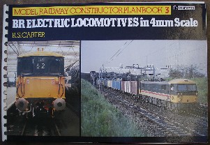
1985, Ian Allan, ring-bound
In stock, click to buy for £14.95
Alternative Online Retailers to Try:
Click here for our prebuilt search for any edition of this book on Abebooks
Click here for our prebuilt search for any edition of this book on Alibris
Click here for our prebuilt search for any edition of this book on Ebay

|
Contents: The book covers the various mainline electric locomotives which have seen service with BR since Nationalisation. The drawings should be viewed for dimensional accuracy, technical details and as line illustrations rather than photographic representations. The line drawings represent the locomotives during their working lives incorporating modifications carried out and different livery schemes applied. In some cases more detailed drawings have been included to explain features of design introduced to overcome specific difficulties encountered: in primary and secondary suspension systems, types of flexible drive employed between motor and wheel, and the collection of power supply from overhead wires or lineside conductor rail, problems which are not always fully appreciated.
Includes the classes:
Class
70 (Southern Railway & BR)
Class 71 (BR/English Electric)
Class 73 (BR & English Electric)
Class 74 (BR/Paxman)
Class 76 (LNER & BR/Metro-Vick)
Class 77 (BR/Metro-Vick)
Class 80 (BR/Metro-Vick)
Class 81 (BRCW/AEI (BTH))
Class 82 (Beyer Peacock/AEI (Metro-Vick))
Class 83 (English Electric)
Class 84 (North British/GEC)
Class 85 (BR/AEI)
Class 86 (BR & English Electric)
Class 87 (BREL/GEC)
Class 89 (BREL/Brush)
Appendix; Former NE Railway Locomotives; Pantographs; Bibliography |
� |
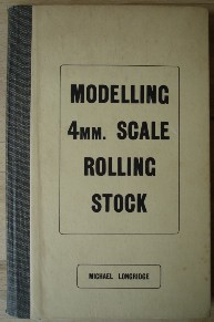
1948, Rayler Publications
Sorry, out of stock, but click image to access prebuilt search for this title on Amazon
Alternative Online Retailers to Try:
Click here for our prebuilt search for any edition of this book on Abebooks
Click here for our prebuilt search for any edition of this book on Alibris
Click here for our prebuilt search for any edition of this title on Ebay |
- Modelling 4mm. Scale Rolling Stock [top]
Written by Michael Longridge; foreword by R.J. Raymond, editor of 'Model Railway Constructor'
First published in 1948 in Great Britain by Rayler Publications, 245 Cricklewood
Broadway, London, N.W. 2, hardcover, cloth binding, 96pp.
in Great Britain by Rayler Publications, 245 Cricklewood
Broadway, London, N.W. 2, hardcover, cloth binding, 96pp.
Contents: The author is one of the pioneers of the 4mm scale on 18mm gauge and his favourite prototype was the late GWR (Great Western Railway). In reproducing in miniature the vehicles of this popular line, he set new standards in modelling practice. His work was often illustrated and greatly admired in the Model Railway Press and many modellers expressed the wish that a book could be published which would show them how to achieve these fine results. This book is the cumulation of that demand. In the pages of this book, the author has fully explained with the aid of many drawings the art of building first-class 4mm models. Whether the gauge adopted is 18mm as in the author's case, or 16.5mm, the instructions are equally applicable as the scale is identical in each instance. Although the vast majority of models illustrated are G.W.R, the constructional principles are the same for any other railway group
Chapters:
1: Introduction, aims and intentions
2: Choice of Materials: wood, card, metal (tinplate, brass, nickel-silver) and considerations regarding underframes, angle sections and windows. The author here also advises the reader to get hold of drawings and photographs to prevent errors occurring in the modelling
3: Underframes and running gear: FOUR-WHEELED - solebars, buffer beam and buffers, axleguards, wheels and axles and brakegear; BOGIE UNDERFRAMES - brakegear; ASSEMBLY OF FOUR WHEELED UNDERFRAME - order of assembly from axleguards to solebars to brake lever ratchet to solebar; ASSEMBLY OF BOGIE UNDERFRAMES - order of assembly
4: Couplings: automatic and non-automatic; merits and demerits of both; automatic coupling designs and non-automatic coupling designs
5: Two-Rail System: A.R. Walkley's method
6: Open Wagon Bodies - Construction - Stage 1 Sides and Ends; Stage 2 - Floor; Stage 3 - Details
7: Closed Wagon and Van Bodies - wood and card bodies; metal bodies; roofs: wood, metal and paper; DETAILS - as in doors and door frames
8: Special Wagons - brake vans, cattle wagons, ventilated vans
9: Passenger Coach and Van Bodies - coach sides, order of assembly (wooden body), windows, compartment partitions; corridor coaches: order of assembly; flush window coaches: assembly of metal sides, ends and floor, or alternatively for metal sides only; assembly of paper sides, roof overhang, flat roofs; Coach Details: vestibule connections, end steps, corridor handrails
10: Painting and Finishing: brushes, underframes, wagon bodies, coach bodies and roofs, and dirt and weathering
Appendix: Some Useful Tools |
1948, Rayler Publications, hbk
Click here for duplicate 1948 hbk listing on Amazon
Click here for 1948 Rayler paperback edition |
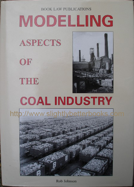
2003, Book Law Publications, hbk
In stock, good condition, click to buy for £36.00 (price reflects scarcity)
Other online retailers to try:
Click here for our prebuilt search for any edition of this book on Abebooks
Click here for our prebuilt search for any edition of this book on Alibris
Or,
click here for our prebuilt search for any edition of this title on Ebay
|
- Modelling Aspects of the Coal Industry [top]
Written by Rob Johnson
Published in 2003 in Great Britain by Book Law Publications in hardback with dustjacket, 96pp, ISBN 1899624430
Original UK retail price: £19.99
Contains 104 high quality black & white plates/photographs
About this book/synopsis: This book looks at the mining, preparation, delivery and distribution of coal, an industry which one employed in excess of a million people. Most of the railway companies in Britain were preoccupied with transporting coal for domestic, industrial or utility purposes; additionally the export market was strong and large. Many British modellers ignore the coal industry, but modelling a coal mine can be one of the more enjoyable parts of modelling in miniature - after all, railways and coal mines are usually found together - one was evolved to serve the other and that relationship continues today, even if the coal mine is abroad and the coal imported! Even when BR ceased to be a customer of coal, when diesels finally banished steam from the tracks, BR continued to freight coal round the country for those who needed and sold it. The large quantities required dedicated fleets of locomotive power and wagons.
The way that the railways carried and carries coal has not stayed static either. Modernisation has seen large numbers of wagons that previously spent long periods in sidings done away with.
This book intends to show modellers how easy it is to model part or all of the aspects of the railway-mining relationship and the activities involved in getting coal from the pithead to the customer. On the way, the book will demonstrate the various methods used by the industry in the way they handle coal - the plant used and some of the important architecture you'd expect to see in the mining industry like the great big mining wheels. Modelling a coal mine doesn't require much space - it may fit on the corner on the layout board just outside of the track curve! And it doesn't have to be on one level - you could have a conveyor, chute or narrow gauge tub system bringing the coal into the washery or screens from the mine up the hill or down in the valley.
There are sometimes different gauges of track to be found in coalmine yards alongside the standard gauge track; and myriads of iron, steel and timber parts and machinery all ready to play their part in the underground engineering feat that is a mine. Mines are usually found on flat or rolling meadow type landscapes or sometimes in a hilly wooded area with maybe a rockface on one side and a river on the other; with the inevitable railway line sharing the flat land. The mines themselves are not one uniform size - small and large mines were and are still to be found.
The author of the book expresses the desire that the book might encourage readers to take up architectural modelling, which may have previously been an area the reader would ignore, or steer clear of. The book has come from years of research, experience and finding out by the author.
Chapters:
Introduction & Introductory Sections:
A Background to the Mine Headframe
Choosing a Prototype
The Models: including scratchbuilding and kits and kit bashing
Creating a Colliery Headframe in 4mm scale including scale diagrams:
Fig. 1. Colliery Headframe, side elevation; and Fig 1A. Plan view of pulley deck (scale 4mm/ft)
Fig. 2. Colliery Headframe, end rear elevation
(scale 4mm/ft)
Fig. 3. Colliery Headframe, end (front) elevation (scale 4mm/ft)
Also a plan layout of a simplified typical colliery alongside two-track main line
Also a diagram of a steel framed self supporting open conveyor bridge for 18-inch wide spoil conveyor, scale 4mm/ft
Also a diagram of a coal handling depot (coal merchants modern (1950s) 2-bay coal/coke storage bunker, scale 4mm/ft
Fig 4. Loading Screens, front elevation, scale 4mm/ft
Fig 5. Loading Screens, side elevation, scale 4mm/ft
Chapter 1. The Collieries
Chapter 2. Industrial Locomotives
Chapter 3. Coal Traffic (Trains & Wagons)
Chapter 4. Exporting the Coal
Chapter 5. The Customers
List of Plates/Photos Included [in order in which they appear]:
Collieries:
- 1955. Leeds Holbeck Engine Shed, showing BR as a customer of coal (coal shute in picture)
- 1968, October. Six Bells Colliery in South Wales. A typical Welsh colliery hogging the valley bottom; winding wheels & railway lines leading up to the colliery in view
- Undated. A colliery railway junction in South Wales
- 1920s. Cardiff Docks- a ship loading up with coal at the quayside from 4 dockside shutes
- 1957. Panoramic view of refurbished Agecroft Colliery near Manchester circa
- 1957, includes railway lines
- Undated. NCB rail network in South-East Lancashire with an Austerity Saddle Tank in action heading a train of coal bound for a washery
- 1921. Gedling Colliery, Nottingham with lattice girder head frames exchanged at a later date for H section girder type towers with Great Northern R1 working from Colwick shed in foreground. Includes piles of wooden pit props
- Undated. Close-up of a conveyor loader at Oakdale Screens
- Undated. Beneath the screens at Denby Hall with a different type of conveyor lowered over a wagon & including an inspection ladder
- Undated, but pre-WW1: Peel Hall Colliery at Little Hulton, nr Bolton in Lancashire owned by James Roscoe & Sons. Shows the mine's fleet of wagons (ten tons, fitted with sprung buffers). An unidentified 0-6-0 is attending to the wagons. Could certainly be accommodated on most layouts. Headgear is made of timber, so most likely built pre-1911
- 1934. Pretoria Pit in Lancashire, which closed shortly after the picture was taken. Larger than Peel Hall with two sets of headgear in view and two winding houses. Loading screens span 6 railway tracks. Headgear is of timber construction (timber headgear
was all replaced by steel in the 1930s)
- 1905. Gibfield Colliery in Atherton, Lancashire built alongside the Bolton-Leigh railway line, with Dutch barn style roofs on the ancillary buildings and a series of elevated walkways wrapped around the main buildings with wooden-sided bunkers attached. Atherton No. 3 0-4-0 outside cylindered tank locomotive in middle foreground with drivers posing for photo on open footplate
- 1935. Gibfield with new lattice steel constructed head frame dominating the mid skyline
- 1963. Gibfield looking South in the year it closed. Only part of the site can be seen, and not much of the mine, but it gives a good idea of what a colliery yard looks like. Shows new NCB weigh office with flat roof and austere brickwork. Original building had pitched slated roof. Shows direct road and rail access to the colliery and despite a few loaded wagons being in view, there is evidence that demolition contractors are at work
- 1887. Faded photo of Bickershaw Colliery near Leigh, Lancashire just six years after coming into production. There are four sets of headgear, each with their own winding houses and seemingly set out in a square configuration. Railways in view. Timber headgear. Dumb-buffered wagons are letter in the house style with semi-elliptical shaped fixed ends
- 1956, April. Mosley Common Colliery with its new coal washery designed to handle Mosley and neighbouring pits' coal. Colliery name is prominently located on the front of the new washery.
- 1930s, Glasshoughton Colliery, near Pontefract, West Yorks. Shows headframes, boiler houses and washery; and many many wagons in the foreground, some of which are Glasshoughton's own and some from Pontefract Collieries' 'Prince of Wales' pit. Of interest in this picture is the aerial ropeway (common at pits at one time), which would have covered distances in miles, taking colliery waste away from the pit head. A portion of a wagon repair shop can be seen
- Undated, Glasshoughton coking plant: 3 chimneys in view, looks like 1 brick & 2 concrete. Again, the railway wagons in view are from Glasshoughton and Pontefract.
- Undated. East Ardsley Colliery, showing timber construction colliery headframes and a collection of timber-built additions around the shafts. The winding house and boilers are the only things showing any permanence. Because the railyard level is set below the surface, this is an ideal candidate scene for modelling, with five chutes on the left feeding the carts and lorries of local coal merchants; and two mine tubs can be seen inverted after tipping their contents on those chutes. The chutes feeding the railway wagons jut out directly from the screening floor
- 1956, July. Calverton departure sidings - shows trackwork with no ballasting! It was probably expected that coal dust would fill in the gaps within a few years
- 1956, Calverton, the new coal washing plant with corrugated asbestos conveyor bridge and concrete columns supporting the building, whereas rolled steel used to perform this job
- 1955, Calverton, showing the pit head on the south side of Oxton Road
- 1920 (circa), Thornhill Colliery (Combs Colliery) in an apparently abandoned state - may have been closed for modernisation (sometimes this took years). Has two headframes in timber, which predominates in this scene structurally whilst the buildings are of brick construction, with slated roofs. General layout of this colliery is on different levels, making it ideal for modelling (enables most of the scene to be taken in without leaning over the baseboard too much). Stone retaining wall also visible in foreground
- 1955. Williamthorpe Colliery, showing the 1939-built washery and screens in a new style to those seen so far in the book. Loading screens span more than 12 tracks and the building face is divided into 3 sections, a design which could be adapted to cover more
- 1950s - set of four photos: North's Collieries Signal Box railway junction, near Tondu looking towards Tondu; (2) away from Tondu; (3) closer to the wagon repairing yard; and (4) looking towards the signal box and further afield to the colliery (North's Parkslip Colliery)
- 1930s. Moorgreen Colliery, Nottinghamshire, showing the new washery (erected 1930s) which served 5 mines. The washery spans 4 tracks and is concrete framed with brick screens filling in the areas between the concrete columns and beams. The washery looks quite imposing, but was only as big as perhaps two railway locomotive coaling towers put together. To the left rear is the rear water tower - this would be awkward to model from scratch, but is of conventional design. A conveyor bridge looks to be under construction on the left feeding the coal and dirt from Moorgreen Colliery itself
- Anytime up to the 1930s. Unidentified view of a colliery yard in the North-East of England belonging to Wallsend & Hepburn Coal Co. Ltd. Sleeper spacing on the railway tracks leading into the colliery are quite large. Shows a side-tipping wagon with simple chain and shackle coupling, timber headgear, and two battery locomotives, which was a rare source of power for collieries at that time. The cauldron wagons to the rear right of the picture would have been over 100 years old at the time of this photo
- 1956, July. Denby Hall, with new washing plant (investment by NCB) with walkway on outside of first floor and spanning six tracks. Over each track there is a gate; the railings are iron. New for the NCB was the use of concrete sleepers on the second and third roads from the right. At this time concrete sleepers were rare even on the main network. The lower picture on page 35 gives a close-up of the left of the upper picture with two staff standing next to the rear wagons of the train heading into (?) the plant
- 1955, Thoresby Colliery departure yard with the colliery itself on the skyline. 8 roads are visible curving round to the right, heading round to the colliery. Headgear and winding mechanisms are nearly identical at this colliery; and the brand winds round a 270 degree cureve to get trains onto the junction at Thoresby Col. Junction. There are two photos of this yard looking in opposite directions
- 1955, July. Oakdale Colliery, South Wales. Shows washery and associated building in simple, austere appearance; ideal for modelling. The buildings use a mixture of concrete, rolled steel joists and columns and copious areas of brickwork. 8 quite new 24.5 ton wagons are in view, each with a white painted plate screwed to the end panel. This plate stated that the wagon was for locomotive coal only and must be returned to Oakdale Colliery. There is a single concrete tower on the right with lone wagon standing beyond, and this is one of the waste buners connected to the main building by a steel-supported concrete footbridge. Includes another photo of the other end of Oakdale washery; and two photos giving close ups of the west end of the Oakdeal washery, looking in detail at the materials employed in constructing the buildings. Shows windows and frames, brickwork, wooden stairs up to a metal observation platform, drainpipes, pulley wheels & cabling, and corrugated materials in use as screens (probably asbestos and steel, old & new, giving clean & dirty, shiny and rusty surfaces for the modeller to replicate). In the 4th view of Oakdale on page 40, the inpsection platform construction can be seen; coats hanging on a bolt and gas mask satchels being used as work bags, lunch bags. Inside the washery, sheep are milling around, which is a nice, unique touch for an inspired modeller to capture
Industrial Locomotives:
- 1963, Wednesday 1st May. Kitson Tank, No. 5358 (built 1921) at Coppice Colliery
- 1964, Wednesday 13th May, 0-6-0 Andrew Barclay No. 1000, Catherine, built 1903, at Gedling Colliery
- 1964, Wednesday 13th May, 0-4-0ST Andrew Barclay, Queen at Gedling Colliery
- 1964, May, 0-6-0ST, Robert Stephenson & Hawthorn, built 1938 and now preserved at Gedling Colliery
- 1964, Tuesday 12th May. 0-4-0, Andrew Barclay 705, built 1891; and 0-4-0 Hunslet 1493, built 1925. All served at Riddings Pye Hill Colliery
- 1959, 12th April. Six Photos at the Central Workshops, Walkden, Lancs:
1) Shows 0-4-0ST Robin Hood, no. 1200, built 1901
2) Shows 0-6-0 outside cylinder ST built by Peckett in 1901, works No. 923
3) Shows 0-6-0ST Wasp based on the successful War Department model. This engine was built by Hunslet in 1954, No. 3808
4) Shows Bridgwater built by Hunslet in 1924, one of the larger engines working the Lancashire coalfield. Was cut up in 1968
5) Shows 0-6-0ST Peckett built in 1890 by Peckett, cut up 1962 at Walkden
6) Shows 0-6-2 tank engine Sir Robert No. 2262. Cut up in 1969
- 1959, May. Two 0-6-0 saddle tank locos: Avonside 2064 of 1931 named ST MARTIN and a quite new Hunslet engine, works 3825, built 1954, numbered 9.
- 1967, June. 0-6-0ST Stanley at Ellenbrook working the coal for the washery at Mosley Common. Photo also features former NSR engine No. 2, which had been bought for preservation
- 1964, May. 0-4-0ST Andrew Barclay No. 1080, built 1908 at Denby Colliery
- 1965, 14th May. 0-6-0ST NCB No. 6 built by Bagnall in 1954
- Undated. English Electric Bo-Bo locomotive of 1951 build, No. 11 in the NCB fleet, seen in use at Tyneside
- 1964, Wednesday 13th May. 0-6-0ST Peter, built by Hunslet in 1943, works No. 2853. at Linby Colliery Nottinghamshire. Ladders can be seen on the footplate (necessary for looking in empty wagons prior to going under the screens)
There are many other plates in the book of coal trains & locomotives; and the export of coal abroad; and the use of coal by its customers, but the important plates are listed above |
�
Modelling Landscapes:
And for the N Gauge Modeller:
Miniature Modelling:
Locomotive Modelling:
Model Train Building:
|
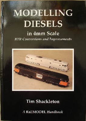
1996. Hawkshill Publishing, hbk
Sorry, out of stock, but click image to access prebuilt search for this title on Amazon
Alternative online retailers to try:
Click here for our prebuilt search for any edition of this title on Abebooks
Click here for our prebuilt search for any edition of this title on Alibris
Or,
click here for our prebuilt search for any edition of this title on Ebay
|
Contents: Despite their excellent overall quality, there are many ways in which today's RTR diesels (Ready-to-Run) can be improved, or "fixed". Not all models come out of the factory with details in the correct scale or position; or maybe you just want to make them a bit more special. by drilling out and expanding new sandboxes for example. This book looks at all these kinds of amendments and part of its appeal is that it tries to imbue the reader with the confidence to start this kind of work-after all, it can be quite daunting to kick off a project on a model that is factory made and ready-to-run.
This book is packed full of practical ideas and techniques to help you upgrade your models-from simple detailing to far-reaching conversions that will enhance the interest and variety of your loco stud. It also shows ways of refining the running quality of modern RTR diesel drives and demonstrates the painting and weathering techniques that result in truly realistic models. The author states that he chose specific projects for this book that would demonstrate, in successive hands-on stages, a way of going about things. The locomotives selected as guinea pigs don't necessarily represent the ones the reader or author would choose to convert or improve, but the way that the author has treated them is-or at least is intended to be-universal. So, what is written about reworking the Lima 37 can easily be applied to the 47, or the 26.
Chapters:
Introduction
1. Tools, Techniques and Attitudes
2. Detailing and Improvements
3. More Advanced Conversions
4. Improving the Running
5. Painting and Finishing
6. Weathering and the Final Touches
7. Suppliers
Index
BR (British Rail/British Railways) Diesel Classes Mentioned:
Class 03 shunter (also pictured, e.g. a line of Class 03s at Norwich Crown point)
Class 04 shunter (also pictured in many reference shots-standard angles high & low)
Class 08 shunter (also pictured, e.g. an old Dublo. Also featured in the preview edition of RailModel Digest)
Class 24 (also pictured, e.g. D5092, one of the first series of BR/Sulzer Type 2s)
Class 25 (also pictured, e.g. the author made a Beyer Peacock class 25/3 from a Hornby Class 25)
Class 31 (also pictured, e.g. the Airfix Class 31 model)
Class 33 (also pictured, e.g. 33009 at Witham Priory, paired with unidentified loco)
Class 37 (also pictured, e.g. the Lima Class 37 model, returned by the author to mid-1960s condition)
Class 40 (also pictured, e.g. the Class 40s roof details as per the Lima model are pictured)
Class 46
Class 47. (also pictured, e.g. 47712 Lady Diana Spencer) at Haymarket. The author converts a Lima Class 47 into the experimental diesel 'Lion', a one-off engine, which had the same 2,750hp Sulzer power plant as the class 47s already in production
Class 56 (also pictured, e.g. 56094 at Knottingley, 1st June 1994 and more. Includes Doncaster & Romanian-built Class 56 details & pictures). The author converts and improves a Dapol Class 56 and this is covered in extensive detail and pictures.
Class 58 (also pictured, e.g. the side view shot from low down giving bogie details)
Deltic
Class 59
Class 60 (also pictured, e.g. view of 60095 'Crib Goch' at Peak Forest, 2nd Sept 1994)
Hymek (also pictured, e.g. D7017 at Weston-super-Mare) on 20th July 1964)
Wisbech tram (looks at a straight drop-fit on the Mainline/Replica/Bachmann Class 03 shunter chassis
Model manufacturers/parts manufacturers mentioned:
A1 Railmatch
Airfix
Alan Gibson
Bachmann
Branchlines
Craftsman
Dapol
Dyna-Drive
Exactoscale
Hashima (motors)
Hornby
Impetus
Lima
Perseverance
Roco
Ultrascale |
�
Diesel Locos on Amazon:
Diesel Locomotives (on the big railway!)
|
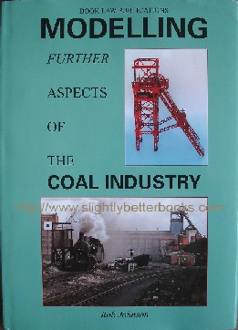
2006, Book Law Publications, hbk
In stock, click to buy new for £22.85
Alternative online retailers to try:
Click here for our prebuilt search for any edition of this title on Abebooks
Click here for our prebuilt search for any edition of this title on Alibris
Or,
click here for our prebuilt search for any edition of this title on Ebay
|
About this book/synopsis: First thing to note is that this book is packed full of mostly black & white photos that provide those modelling the coal industry and those modelling industrial railways (or railways with coal elements) with a lot of visual detail on the mining industry in the UK.
Following on from the 2003 hardback edition of Rob Johnson's 'Modelling Aspects of the Coal Industry', ISBN 1899624430, published by Book Law Publications; this volume makes more material on the coal industry available to the modeller, much of which has come from sources and people other than the author. Most significantly, the material has allowed the author to include actual photos and details of the models themselves, something which was absent in the first volume. The illustrations of the models show headframes, associated buildings, locomotives, wagons and much more. The book also includes adverts from suppliers and manufacturers that offer coal-related items. Some collieries with detailed pictorial focus are: Astley Green (West of Manchester) and Snibston (Leicestershire). Pictures of the models themselves include photos of the Wrightscale colliery headframe kit, available in 2mm and 4mm scales (at the time of this publication); Michael Edge's Coed Cae Colliery (part of his Cwmafon layout), and Herculaneum Dock.
Chapters:
Introduction
The Colllieries
Delivering the Goods (contains 19 plates, mostly of locomotives)
Industrial Locomotives (contains 25 plates, mostly of locomotives)
Industrial Locomotive Facilities (contains 14 plates, mostly of locomotives)
Wagons, Wagons, Wagons and other vehicles (contains 23 plates, mostly of locomotives). Contains a real social history 1920 photograph of twenty-nine members of the New Moss Colliery, standing and kneeling in front of a nicely weathered 12-ton, 5-plank, end door coal wagon
Astley Green Colliery-an "exposé" of photographs
Snibston Colliery-an "exposé of photographs"
The Models
Manufacturers, Suppliers and Services
Select list of Plates/Photos Included [in order in which they appear]:
The Collieries:
- 8th March 1967, LMS Fowler 3F 0-6-0T "Jinty" 47313 (built by Bagnall's); and 47289 (built by North British) enjoy a new lease of life under the NCB (National Coal Board). Both are shown in this image hauling coal trucks at Williamsthorpe Colliery. Of interest to the modeller capturing detail is the tarpaulin and adjacent can on the footplate of 47313; plus lineside hut with 'Keep Out' scrawled on the side.
- 1966, May. Kirky Colliery No.1 shaft headframe, NCB East Midland Division. Construction - mixture of lattice and rolled steel girders. Four main legs are lattice girders with plating covering the two legs nearest the winding house (probably to give added strength to the legs when heavier, higher capacity cages or skips were introduced in the late 1950s/early 1960s)
- 1970s. Astley Green No. 2 headframe
- Pre World War 1. Nostell Colliery nr Wakefield. Timber headframe of downcast shaft is surrounded by the screens and associate pit buildings, of simple wooden construction. Winding house is typically brick built, as is the boiler house with its six Lancashire boilers showing their faces to the yard
- 1970, 16th July. Cadley Hill Colliery with steel framed screens and corrugated asbestos-clad building, with a steam engine in the foreground - RSH 7298, an 0-6-0ST of 1946. The wagons in the picture are thought to be the former BR 21-ton, double door coal wagons, each with CH and fleet number crudely painted on the side
- 1970, May. Widdrington opencast mine with ex-BR J94 No. 68078, designated L2 working the site, here approaching the screening plant with a load of raw coal from the large open pit. In model form, this pit would be an ideal choice because it would not be too much of a challenge. The buildings in shot are all on stilts and clad in corrugated materials
- 1955. Under the screens at Brodsworth Colliery, with 21-ton Loco Coal wagons being loaded. The loading conveyor is just visible. It is noticeable from this picture that the clearance is limited under the screens once wagons are full; and the supporting columns are cast in concrete
- 1970, April. Wheldale Colliery, Yorkshire. Photo shows red liveried steam engine Hawthorn Leslie 0-6-0ST HL3534 (built 1922), NCB No. S115 named Frank. Shows some interesting architecture - the enclosed conveyor housings and walkways are steel framed with brick in-fill cladding, going off at different angles and gradients. The closeness of other buildings is noticeable, as is the apparent random fixing of cables
- 1936. Astley Green Colliery: the new washery at the east end of the yard. In the foreground are the dead-end sidings in which loaded wagons were parked prior to collection. 4 rows of wagons are parked, the left hand one of which seems to be full of dirt, whilst the others have different grades of small coal. The wagons all carry the Manchester Collieries 'M' logo.
- Late 1920s, West Riding Colliery, close-up photo of a steel framed bunker with hoppers for coal merchants, with brick infill walls
- Undated. Overhead view of demolition of No. 2 headframe at Astley Green Colliery
- 1971, April. Grimethorpe Colliery -photo shows the construction and cladding of the conveyor housing. Framework is mostly made from rolled steel in L and H sections with corrugated asbestos on the sides and curved roof sections. The background is dominated by two large venilation shafts sending power-assisted fresh air into the mine, with massive concrete ducting needed (as here). Also visible just beyond the conveyor is now redundant 0-6-0ST No. 4, a Vulcan Foundry 1945-built No. 5295, ex WD 75305 with new headlight on front of the tank
- 1964, Pye Hill Colliery, showing the 'main line' with Andrew Barclay outside cylinder steam locomotive making its way to the engine shed on the right. This view also shows what is probably terraced housing for the collieries workforce in the background abutting the colliery's sidings. There are concrete street lamps present with elegant swan necks - strangely these grace the 'main line' rather than a public road as you'd expect. There is a sleepered road crossing with a dirt covering. On the left of the photo is a Ruston Bucyrus RB-22 drag line excavator; and on the right a period Morris van, registration SWB 72(?)
- 1954, Summer: Wath marshalling yard. This installation had as its purpose the marshalling and dispatching of coal from the South Yorkshire collieries to the hungry mills, factories and industrial concerns of South Lancashire, a role it had carried out since 1907. There are two views of this yard on page 10: the top one showing a Robinson 04 on the left of the picture which has just arrived on a coal train. On the right of the picture are two double-heading Darlington-built 350 h.p. 0-6-0 diesel shunters. There were only 5 of these based at Wath, numbered 13060-13064 (later D3060-D3064). These shunters appear to be pushing a loaded train 'over the hump' and into the yard.
The lower picture gives a good overview of Wath Central with the marshalling yard in the left background. Spoil heaps dominate the centre and right background, with even the permanent way having a covering of what looks like coal dust in view. The two diesels in the top picture appear to be heading south on the mainline with the same train in the bottom picture
|
Industrial Locomotives:
4mm Scale Models
|
1975, Model & Allied Publications
Sorry, out of stock, but click image to access prebuilt search for this title on Amazon
Alternative online retailers to try:
Click here for our prebuilt search for any edition of this book on Abebooks
Click here for our prebuilt search for any edition of this book on Alibris
Click here for our prebuilt search for any edition of this title on Ebay
|
- Plans Handbook 2: Model Boats & Cars [top]
First published in 1975 in Great Britain by MAP Plans Service (Model & Allied Publications), paperback, 86pp, plus order-form at the rear and Autumn 1975 price-list and index in blue paper, giving model, plans number, page & price.
Original UK retail price: £0.30
Contents: Profusely illustrated & detailed, this publication served as a catalogue to all the model boats & cars plans that Model & Allied Publications published. The book often gives pictures of the craft or vehicle that the plan will build or illustrates; along with the name of the creator of that model, like Vic Smeed (creator of many models such as the Scorcher car, which uses Meccano gears and inexpensive wheels) or G. H. Deason (creator of the 1898 Benz Doggart model).
The catalogue even details some more futuristic models such as 'Mr. Robotham', an ingenious 2ft high walking robot powered by two small electric motors, which was created by Peter Holland (plans MM/406). Also very futuristic is 'Teal' by Peter Holland, which was a strangely bird shaped tripedal electronic ambulatory locomotive powered by a small electric motor (plans MM/380).
The book's value of course lies principally in its listing what plans MAP published in this area, so the potential model-builder can know for certain that plans exist and then make efforts to track them down. Please note that despite the claims that the book looks at plans of cars too, it is mostly dominated by model boats.
In summary, plans listed cover recent additions, tugs, lifeboats, straight runners, trawlers, service launches, miscellaneous workboats, scale ships, semi-scale ships, paddle steamers, warships, submarines, waterline drawings, competition models, semi-scale sports models, scale cabin cruisers, hydroplanes, airscrew hydroplanes, Unorthodox, Scale Sailing Ships, Period Ships, Non-Class Yachts, Class Yachts, Hovering Craft, Unusual vehicles, working cars, prototype car plans. Articles and Notes: How to Order, Glass-fibre Hull-Fitting, Ply, Model Boat Radio, Building from Plans, Hull Construction, Star Grading System, Power Boat Competition Classes, Scaling Plans, Working from Lines, Model Yacht Classes, Beginners Choice, and finally How to Solder |
�
Plans Handbook 1
Plans Handbook 3
|
1974, MAP
In stock, click to buy for £7.25, not including p&p
Alternative online retailers to try:
Click here for our prebuilt search for any edition of this book on Abebooks
Click here for our prebuilt search for any edition of this book on Alibris
Click here for our prebuilt search for any edition of this title on Ebay
|
- Plans Handbook 3: Model Engineering [top]
First published in 1965 in Great Britain, then reprinted in 1965, 1966, 1969, 1971, and 1973.
Republished in 1974 in Great Britain by Model & Allied Publications in paperback, 96pp.
Is a catalogue of all the model engineering plans published by MAP, with prices (as of 1974)
Original UK retail price: £0.20
**Please note this book does not contain actual plans**
Contents: Published in 1974, this paperback lists every set of working model drawings published by Model & Allied Publications Ltd (formerly Percival Marshall). As such it is invaluable for listing what plans are out there for aspiring model engineers trying to build particular models, such as Martin Evan's Simplex locomotive. The book lists out plans for locomotives, traction engines, steam engines, petrol engines and workshop equipment. Some of the main plans of interest are from some celebrity engineers such as L.B.S.C, Edgar T. Westbury, W. J. Hughes, Duplex (Ian Bradley & Norman Hallows), Martin Evans, John Maskelyne and more. The book also includes key general model engineering information such as Screw Cutting Tables, Standard Threads, Wire & Sheet Metal Gauges, etc.
Interestingly the book makes recommendations for the beginner to start model engineering:
[The L.O. numbers are the numbers of the plans]
L.O 27, "Rob Roy", a 3.5 inch gauge 0-6-0 Caledonian Railway Tank Engine by Martin Evans (see Martin Evans listing here)
L.O. 75, which is LBSC's "TICH" in 3.5 inch gauge - an 0-4-0 Tank Locomotive (see Martin Evans listing here)
L.O. 40, "Caribou" for the North American enthusiast. This locomotive is a 0.75 inch scale Canadian National 0-8-0 Switcher for 3.5 inch gauge (see Martin Evans listing here)
And, good models for the club track are recommended as:
L.O. 26, "Springbok", a 5 inch gauge 4-6-0 Class B1 Locomotive by Martin Evans, a large and powerful model ideal for club tracks, but achievable in a modest workshop
L.O. 32, "Firefly", a 5 inch gauge version of a GWR 2-6-2 tank engine of the 45XX class by Martin Evans, achievable on an average 3.5 inch centre lathe
L.O. 936, "Nigel Gresley", a 5 inch gauge G-N-R 2-8-0 locomotive by Martin Evans
For the advanced builder, L.O. 18 was recommended, which is "Twin Sisters", a 5 inch gauge L.M.S 0-6-0 Class "2F" Tank Locomotive by J. I. Austen-Walton, an accurate coal-fired scale model of the Fowler dock tank with outside cylinders
Contents:
1) Locomotives (Westbury, Austen-Walton, Martin Evans
2) L.B.S.C Locomotives
3) Petrol Engines (Edgar Westbury)
4) Other Petrol and Diesel Engines
5) J. N. Maskelyne Locomotive Drawings
6) Traction Engines
7) Miscellaneous Engines
8) Steam Engines
9) Miscellaneous
10) Workshop Equipment
11) Sundry Models
12) Lineside Models by J. H. Ahern
13) Outline Locomotive Drawings by J. N. Maskelyne
14) Railway Features Drawings by E. F. Carter
15) Locomotive Transfers.
General Model Engineering Information and tables of data:
a)
Screw Cutting Tables for Myford ML 7 and Super 7 Lathes
b)
Standard Threads
c)
Hexagon Bolt-heads and Nuts: Taper Pin Reamers
d)
Standard Taper Shanks and Sockets
e)
Headless Steel Socket Screws-Steel Grub Screws
f)
Hand Reamers: Draw-in Collets: Shrinkage allowance
g)
Standard Letter & Number Drills: High Temperatures
h)
Wire & Sheet Metal Gauges
i)
Miscellaneous Modelling Information |
�
Plans Handbook 1
Plans Handbook 2
Model Engineering Books on Amazon:
|
1973, Model & Allied Publications, pbk
Alternative online retailers to try:
Click here to access our prebuilt search for this title on Abebooks
Or click here to access our prebuilt search for this title on Alibris
Or click here to access our prebuilt search for this title on Ebay
|
- Private-Owner Wagons [top]
First published in 1973 in Great Britain by MAP Technical (Model and Allied Publications Ltd), in paperback, 48pp, brown card covers, staple binding, ISBN 0852423438 . Specialist Booklets No. 11 . Specialist Booklets No. 11
About this book/synopsis: The private-owner wagon became obsolete when the National Coal Board was founded in 1948, but this does not mean that this subject area is redundant simpley because it remains of great interest to both the transport and railway enthusiast and, or historian; not forgetting invaluable for those railway modellers who wish to have authentic stock on their period layouts. The wagons are of great interest because there are so many different types and all in different colour schemes and styles. Some came in company livery; others with advertising slogans on them. In the years when they could be seen often and freely on the railways, information on them was not collected to any extent; as with anything that's ordinary and plentiful, they were overlooked. When they began to disappear through obsolescence, there was a belated effort to preserve their memory with drawings and photographs and this book presents a variety of scale diagrams and authentic photographs of some of these unique wagons. Main dimensions, history, general information and livery styles are noted along with the photos where they are available.
Chapters:
1. The Chauldron Type Wagon & Other Early Period Examples
2. Some Unusual Examples
3. Differences between R.C.H. (1887) and (1923) Standard Wagons, with Additional Material of Interest
4. The Correct Operation of Private-Owner Wagons
5. Some Area Examples
6. Rail Tank Wagons. [Note - sections include wagon load weights and wheel base lengths]
Illustrations Included: (dimensions given in imperial measurement: feet and inches)
p1 (title page). Garth Merthyr Colliery. G. M. Masteg. Tare 3-13-0. Load 7 tons
Chapter One. The Chauldron Type Wagon and Other Early Period Examples
p6. Scale diagram, side elevation of South Hetton chauldron-type wagon showing grab handles (wheelbase 6ft)
p6. Scale diagram, side elevation of "South Hetton" chauldron-type wagon. Wheels and grab handles design and position shown (wheelbase 6ft)
p7. Photo: a vintage view of some of the wagons operated by Bath Stone Firms Ltd (later known as Bath and Portland Stone Firms Ltd), here stationary at Corsham Quay, Somerset. The photo is inherently valuable for its vintage, but it shows another rare type of private trader wagon used for the conveyance of china clay. This had sides of only one or two planks depth, very different to the depth of wagon used on the railways. Photo: Kingston Minerals Ltd.
p7. Scale diagram, side elevation of South Hetton chauldron-type wagon showing grab handles (wheelbase 4ft 6")
p7. Scale diagram, length-wise view of South Hetton chauldron-type wagon showing grab handles and journal sleeves (wheelbase 4ft 6")
p8. Sketch diagram showing side elevation of a dumb-buffer type (ex) private owner colliery wagon from Camerton Colliery (near Radstock), tare 5-10-0, load 8 tons, #189
p9. Sketch-drawing showing end elevation of a dumb-buffer type (ex) private owner colliery wagon
p9. Sketch-drawing of the brake gear used on many "early-type" 6-7 tone ex "private-owner" wagons
Chapter Two: Some Unusual Examples
p12. Photo, side view, of Ministry of Munitions (MM) 20 ton wooden hopper waggon, #10344, tare 8-11-0. On the side "Empty to Northants Ironstone Co., Byfield, S. & M.J.R".
p12. Photo, side view, of Arthur H. Stabler, Darlington 10 ton non-convertible type coke wagon. Non-convertible means that the coke raves could not be removed from the wagon sides. Load 10 tons, tare 6-18-0
p.13. Scale drawing - side elevation of 7 ton (ex) "Private Owner" wagon, Garth Merthyr Colliery, G. M Maesteg, Tare 3-13-0, Load 7 tons. Wheelbase: 5 ft. 6 in.
p.13. End elevation of 7 ton (ex) "Private Owner" wagon, Garth Merthyr Colliery, G. M. Maesteg. Wheelbase: 5 ft. 6 in
p.13. Photo, side view of Charringtons 12 Ton Steel Constructed Wagon #7190, built by the Butterley Engineering Co. Ltd. in 1935-36, tare: 6-18-2
p.14. Side elevation scale drawing of Horlick's Malted Milk 10 ton wagon No. 1built in 1930 by G. R. Turner & Co. Ltd of Langley Mill, Notts. Brakes and main dimensions accord with the R.C.H. (1923) specifications. Tare: 7-11-1; Wheelbase: 9ft
p.14. Photo, side view, Butterley Steel Wagon #5584, built to the Butterley patent design in 1935 and 1936, tare: 7-1-0
p.14. Photo, side view, P & J R A10 two-plank convertible wagon (P & J R stands for "Pontop & Jarrow Railway", a private colliery in North East England). An interesting example of a convertible coke or breeze wagon. Tare: 5-15-1
p.15. Photo, side and end view of Crawshay Brothers Cyfarthfa, Merthyr Tydfil, No. 136, 8 tons load, tare: 4-12-3. This is a peak roof wagon for conveying lime (peak roof means slanted)
p.15. Photo, side and end view of W.I.&S.Co. Ltd, Workington (Workington Iron & Steel Company) private owner brake van No. 2
p.16. Side elevation scale drawing of Black Park Colliery (Ruabon) wagon with unusual and exotic livery, 10 tons load, tare: 5-19-0
p.16. Photo: side and partial end view of Allsopp's Lager Beer wagon No. 4 - an 8 ton van for conveying Lager Beer (obviously!). Tare: 10-0-0. Vehicle was ventilated and fitted with vacuum brakes enabling fast traffic workings
p.17. Photo: side view - Alfred Hickman Ltd., Spring Vale Furnaces, Nr. Wolverhampton #365, Load 20 tons, steel type hopper wagon for conveying iron ore, which would have worked in circuit between Caernarvon and Wolverhampton. It was built in 1919 by the Midlands Railway, Carriage & Wagon Co. Ltd., (taken over by Metro-Cammel Ltd.) and registered by the L. & N.W. Railway Co. Tare: not certain, likely to be 8-6-0. Brakes were fitted both sides with a wheelbase of 9ft
p.18. Photo, side & partial end view of 12 ton Murphy Brothers Ltd., Waterford, Eire, (BG) private-owner wagon #33. Load 12 tons; tare: 6-2-0
p.18. Photo, side view of possibly ex B.& C.D.R. vehicle hired to the private-owner East Down Shire Steam Ship Company Ltd. of Dundrum, Northern Ireland. The wagon was fitted with 3-hole type disc wheels and a brake lever. Photographed in 1949 by D.G. Coakham
p.18. Photo, side and end view of an Imperial Chemical Industries (ICI) 5 plank, 12 ton wagon for the conveyance of salt, load 7 tons; tare: 7-8-0
Chapter Three: Differences between R.C.H. (1887) and (1923) Standard Wagons, with Additional Material of Interest
p.19. Two photographs of wagon underframe component parts including brake levers, brake shoes, brake lever racks, and "V" type brake hangers, all built by The Cambrian Wagon Co. Ltd (in 1973 this was part of Powell, Duffryn Engineering Co. Ltd)
p20. Detailed scale drawing, side elevation, of standard mineral wagon with wood body and steel or iron underframe (ex private-owners), as built to conform to one of the R.C.H. pre-1923 type specifications. Lower drawing is a top (overhead) elevation
p.21. Half of a detailed end-elevation scale drawing of an 8, 10 and 12 ton wagon, December 1907
p.22. Detailed scale drawing, side elevation of a 12 ton typical private-owner wagon as built to the Railway Clearing House (1923) specifications, not letter so that the dimensions can be clearly seen. The arrangement is of a timber underfram mineral wagon. Lower drawing is of a top (overhead) elevation and the top drawing on page 23 is the end elevation, again with detailed measurements
p23. Photo, side view of "The Cambrian Wagon Co. Ltd. Builder of the 1923 Standard Wagon. 1923. Cardiff. Tare: 6-19-0; Load 12 tons" - a typical private owners mineral wagon as built to the R.C.H. 1923 specifications
p.24-25. 4 rows of detailed scale drawings, taking up pages 24-25 and looking at end, side and overhead elevations of 5, 7 and 8 plank R.C.H standard 12 ton open wagons (company and private-owner). Drawings show iron capping to top edge, door catch, floor, "Gloucester" axlebox (G.W. S.R & Most P.O), wheels (spoked or 3 hole disc), reversing cams, rail to underside of solebar, body planking, register plate, horse hook, label clip, door stop and independent brake gear. Potential variations are noted on page 25
p.26. Photo showing a group photo staged in front of a (side view of a) Newton, Chambers & Co. Ltd. Thorncliffe Izal wagon. It's a typical example of the pride a company and its employees felt in owning a new wagon; and it manifested itself in a photo shoot
p.26. Side view (in front of a red-brick building) of a 30 tons internal use plate wagon, #78, of the Appleby-Frodingham Steel Company, Scunthorpe. The wagon was used to convey steel plates and the lettering on the side reads 'To run between plate mill and pickling plant only'
p.27. Photo - side and end view of Measham Collieries Limited, Measham, wagon #248, a typical private-owners wagon as built to the R.C.H. 1887 specifications, load 10 tons, tare: 6-8-0
p.27. Photo-side and end view of Coke Breeze Internal A-F S Co. #875 - a 25 ton internal use coke and breeze wagon of the Appleby-Frodingham Steel Company, Scunthorpe
p.27. Photo showing how some private owner wagons were converted into seven plank types; this one from Brown Bayley's Steel Works, Sheffield, wagon #21
Chapter Four: The Correct Operation of Private Owner Wagons. The notes recorded in this chapter are mainly added to help model railway enthusiasts
p.28. Photo of a 20 ton hopper wagon which, although built in 1938, bears a similarity to the steel-type hopper being used in the 1970s (and later) for house-coal supply. The wagons were numbered according to the requirements of various private owners
p.29. Side elevation of Pwllheli Granite Co. Ltd. wagon #167, Minfford & Gimlet Rock, Pwllheli; tare 5-4-1, load 10 tons
p.30. Photo of side and end view of a Thomas Ness Limited (Black Banks Chemical Works, Darlington) 14 ton rectangular type rail tank wagon #103, which apart from conveying chemical traffic, would occasionally have been seen in gas works sidings from where it would have conveyed Tar Resioval products to the chemical manufacturers; tare: 9-3-0, load 14 tons
Chapter Five: Some Area Examples
p.32. NORFOLK. Side elevation scale drawing of E.T. Ketteringham Koal Merchant, King's Lynn, wagon #30, tare: 6-7-0, load 12 tons. Diagram shows location of builder's plate, "register plate" and label clip
p.32. Small size side elevation scale drawing of H. Fulcher, Norwich wagon retaining a horse hook under the words "City Station" on the side and above the axlebox. Wagon is number 5, tare 5-10-0, load 10 tons
p.32. LONDON. Side and end elevations of Stevenson, Clarke & Co. Ltd wagon #21, tare 6-0-1, load 10 tons
p.33. Side elevation scale drawing of "Why Not Call Us Over The Coals? Telephone 1170. GOWS London" wagon no. 3, tare 6-0-0, load 10 tons. Gows was a coal merchant
p.33.
Photo showing side and end of Rose Smith & Co.Ltd., London 8 plank (R.C.H 1923) Type Wagon, built by the Gloucester Railway Carriage & Wagon Co. Ltd. It had 8 planks instead of the normal 7. Tare: 7-5-0, load 12 tons
p.34. KENT. Side elevation scale drawing of John Perry & Co. Coal Merchants of Broadstairs and Ramsgate wagon No. 13, tare 6-0-0, load 12 tons
p.34. LANCASHIRE. Photo of Blackpool Co-operative Society Limited
wagon No. 32, tare 6-6-1, load 12 tons. This wagon is particularly interesting for the Beehive emblem painted on the side doors. The wagon was built in 1906 by Hurst Nelson & Co. Ltd, and was registered by the L. & Y. Railway Company. Wheelbase 9ft. In later years, the beehive emblem was taken off and the brake gear modernised to R.C.H (1923) specifications
p.35. Side elevation scale drawing of The Clifton Steam Trawlers Co. Ltd. Fleetwood Fish wagon No. 2, tare 7-11-1, load 12 tons
p.35. WARWICKSHIRE. Side elevation scale drawing of "H.P." Sauce Works, Aston Cross, Birmingham wagon No. 1, tare 6-0-0, load 10 tons
p.35. WORCESTERSHIRE. Side elevation scale drawing
of Earl of Dudley, Baggeridge Colliery wagon No. 675, tare 6-0-0, load 12 tons
p.36. SOMERSET. Side elevation scale drawing of Dunkerton Coal Factors Ltd. wagon No. 5071, near Bath, tare 6-0-0, load 12 tons
p.36. CHESHIRE. Side elevation scale drawing of Chester Railway Employees Coal Association Wagon No. 7, Chester, tare 6-10-0, load 12 tons
p.36. STAFFORDSHIRE. Side elevation scale drawing of Neatherseal, Burton-on-Trent wagon No. 871, tare: 6-11-0, load 12 tons
p.37. DEVON. Side elevation scale drawing of Bovey Pottery Co. Ltd., Bovey Tracey, Newton Abbott wagon No. 2, tare 5-18-0, load 12 tons
p.37. WILTSHIRE. Side elevation scale drawing of The Avon India Rubber Co. Ltd., Melksham, Wilts, wagon No. 2, tare 6-8-0, load 12 tons
p.37. DERBY. Side elevation scale drawing of Brookside Johnston Ltd., Derby, Coal Merchant, wagon No. 8, tare 7-0-1, load 12 tons
p.37. Side elevation scale drawing of Arthur Underwood, Coal Merchant, Hope Village, wagon No. 5, Tare 6-0-0, load 10 tons showing spoked wheels and where you would grease the axelboxes
p.37. LIVERPOOL. Side elevation scale drawing of J. Tharme, Liverpool wagon No. 8, tare 5-18-0, load 12 tons
p.38. LINCOLN. Side elevation scale drawing of Warrener, Coal Merchant, Lincoln wagon No. 3, tare 5-19-2, load 10 tons. Livery G.W.R. green
p.38. CORNWALL. Side elevation scale drawing of Thomlin & Co., Truro wagon No. 1, tare 6-10-0, load 12 tons
p.38. CUMBERLAND. Side elevation scale drawing of Foster Bros, Carlisle No. 1 wagon, tare 5-18-1, load 10 tons
p.38. NORTH EAST ENGLAND. Side elevation scale drawing of Wallsend and Hebburn wagon No. 71, tare 6-10-0, load 12 tons
p.39. YORKSHIRE. Side elevation scale drawing of King Cole & Co. Ltd., Sheffield "King Cole Sells King's Coal" wagon No. 7, tare 7-1-0, load 12 tons. Main dimensions and brakes conform to R.C.H. (1923) specifications. The wagon was built by R. Y. Pickering & Co. Ltd and was registered by the L. & Y. Railway Co.
p.39. HERTFORDSHIRE. Side elevation scale drawing of New Monckton Colliery Co. Ltd., Royston wagon No. 8701, tare 7-1-0, load 12 tons. Of interest due to unusual placing of lettering of collliery name at the opposite side of the doors
p.39. SUSSEX. Side elevation scale drawing of James Chandler, Lewes, L.B.S.C Railway wagon No. 1,
tare 5-19-0, load 10 tons
p.40. SCOTTISH AREA. Photo showing side and end view of a Bredisholm wagon No. 100, tare 5-14-3, load 8 tons, built by Hurst, Nelson & Co. Ltd. as early as the year 1897. It should be taken as a typical example of a four plank 8 ton colliery wagon from Scotland. It was registered by the Caledonian Railway Company. Wheelbase: 7ft 6 inches
p.40. Side elevation scale drawing of Greenhill Colliery Co. Ltd., Greenhill Colliery Brickworks wagon No. 334, tare 5-10-0, load 8 tons
- a typical Scottish area mineral wagon fitted with three coke rails
p.40. Side elevation scale drawing of W B & Co Ltd., (William Baird & Co. Ltd) Twechar, Kilsyth wagon, an 8 ton non-convertible type coke wagon, tare 5-10-0: a typical Scottish area private-owner wagon
p.41. Side elevation scale drawing of The Alloa Coal Company Ltd., Alloa wagon No. 1375, tare 7-3-0?, load 12 tons
p.41. Side elevation scale drawing of Nairn Gaslight Company, Nairn wagon, tare 6-11-0, load 12 tons
p.41. WALES. Photo showing side and partial end view of The Cambrian Wagon Company Ltd. (in 1973, this was part of Powell, Duffryn Engineering Co. Ltd) 12 Ton Standard All Metal Tarmacadam Wagon, tare 6-10-0, load 12 tons - used for conveying tarmacadam and road stone. This type of wagon was comparatively rare, so the photo is of particular interest. It was built in April 1923 conforming to the R.C.H (1923) specifications. Fitted with "T" section end stanchions. Wheelbase 9ft.
p.41. Side and end elevation scale drawings of Welsh Navigation Steam Coal Co. Ltd. Cardiff wagon No. 1072, tare 7-11-1, load 12 tons
p.42. Side elevation scale drawing of Elizabeth Merideth Jones Coal Merchant Blaenau Ffestiniog wagon No. 3, tare 6-0-0, load 10 tons. This wagon is unusual simply because the coal merchant business in this case was run by a woman
p.42. Side elevation scale drawing of the Eifionyd Farmers Association Ltd., Phwllheli wagon No. 17, tare 6-0-0, load 10 tons
p.42. Side elevation scale drawing of N. Dowell, Coal Merchant, Prestatyn wagon No.1, tare 6-0-0, load 10 tons
Chapter Six: Rail Tank Wagons
p.43. Photo showing side and end view of Esso No. 2156 - a class "B" 14 tons Bitumen Rail Tank Wagon, an anchor-mounted tye vehicle built in 1944 and fitted with steam coils to keep the load liquid in transit. The bitumen was discharged by a hand wheel operated valve through a discharge pipe visible under the solebars on the near side in the photo. Anchor mounting appeared in 1942 and replaced a method of fixing a tank barrel to a chassis with tierods and strapping
p.43. Side and end elevation scale drawings of Liquid Chlorine hutched-type internal cylindrical rail tank wagon. Here the cylindrical tank is fitted within the wagon body. Wagon No. 1750, tare: 9-0-1, load 14 tons
p.44. Two photos showing side and end views of Independent Milk Supplies Ltd Hygienic Milk Tank Service - a 14 ton rail tank wagon, tare: 23-11, load 14 tons. Wheelbase 12 ft. The milk tank wagons are some of the rarest examples of rail tank wagons. The wagon was built in the mid 1930s with the painting dating from 1936.
p.44. Photo showing a side and end view of a similar wagon after its livery and lettering had been changed in 1940. Interesting to note that the two photos at the top of page 44 show the wagon with G W painted on it (Great Western), whereas the 3rd photo shows the letter "W" painted on the solebar to signify Western Region
p.45. Photo showing side view of The Burnden Tar Co. (Bolton) Ltd. wagon no. 10, 12 tons rectangular type rail tank wagon, tare 8-11-0
p.45. Side and end elevation scale drawing of R. S. Clare & Co. Ltd., Liverpool - side and end elevations of 10 ton rectangular tar tank wagon, tare 7-8-1, load 10 tons
p.45. Photo showing side and end view of a British Hydrocarbon Chemicals 29 tons modern-type rail tank wagon built by British Railway & Electric Co. Ltd.
p.46. 2 photos showing side and end view of Ind Coope Ltd., Burton-on-Trent 11 tons Rail-Tank-Wagon No. 22, for brewery traffic ("Broad-side" elevation photograph). Interesting for its contrasting style to chemical and petroleum wagons, this brewery wagon was built by Charles Roberts & Co. Ltd., Wakefield in 1938
p.46. Side and end elevation scale drawing of Pratts Spirit, "Write for Prices", Anglo American Oil Co. Ltd., London. Tare: 9-7-0
p.47. Photo showing side and partial end view of British Petroleum Co. Ltd. rail tank wagon No. 557, with two manhole filler domes. This is an early vintage rail tank wagon
p.47. Side elevation scale drawing of a typical rail tank wagon applicable to the 1927 era and onwards
p.48. Side, end and underneath scale keyed drawing of a rectangular type rail tank wagon with 30 of the major components labelled and named
p.48. And finally, an end view scale drawing of a typical rail tank wagon from 1927 onwards
|
Other Books on Private-Owner Wagons:
Railway Wagons:
Wagons to Scale:
Railway Wagon Books for Modellers:
Freight on the Railways of Britain:
Freight Trains:
|
1981, TEE Publishing, pbk
In stock, very good condition, click image above to buy for £11.00, not including post and packing, which is a further £1.75 for UK buyers, more for overseas customers. 1st class & international postage available
Alternative online retailers to try:
Click here to access our prebuilt search for this title on Abebooks
Click here to access our prebuilt search for this title on Alibris
Click here to access our prebuilt search for this title on Ebay to access our prebuilt search for this title on Ebay
Click here to access our prebuilt search for this title on Biblio
|
About this book: In the pages of this book, the authors have endeavoured to provide the reader with all the information necessary for a proper assimilation of the details of the subject both in theory and practice. Much time and effort have also been devoted to the preparation of the drawings, many of which have been specially plotted to afford a graphic and more easily understood exposition of the numerous points referred to in the text, as, without the aid of such a medium, the task of making everything as clear as is desired would be rendered much more difficult. It is not to be expected that in a work of this kind and size every type of valve motion adaptable to locomotives could receive treatment. The endeavour has been made however, to include all the types nowadays in common use, together with some of the earlier forms of gearing now for the most part discontinued, and a few examples of the less familiar ones which either in this country or abroad have at one time or other enjoyed a certain vogue. The choice and design of valve is important - they enable a locomotive to function. An inefficient gear will reduce the power output and interfere with smooth and free running, but it will also adversely affect the steaming qualities of even the most excellent boiler with the result that the engine will not be able to properly do its allotted work
Contents:
Preface
1. Cylinder, Connecting Rod, Crank and Eccentric
2. Slide Valves
3. Piston Valves
4. Cycle of Events and Their Characteristics
5. Link Motion Valve Gears
6. Radial Valve Gears
7. Walschaerts Type Gears
8. Valve Gears for 3- and 4- Cylinder Engines
9. Limiting and Regulating Cut-off
10.
Poppet Valve Gears
11. Rotary Cam Gears
Illustrations
Frontispiece: B&W photo of 2340, Prince of Wales, which was a locomotive fitted with the Beames valve gear - an arrangement of the Walschaerts gear, by means of which the valves of inside-cylinder engines can be operated by an outside valve-gear
Chapter 1. Cylinder, Connecting Rod, Crank and Eccentric
p10. Fig. 1. - alphabetically-labelled diagram showing a layout of cylinder and valve gear
p12. Fig. 2.
- alphabetically-labelled diagram of the eccentric, crank pin and connecting rod. Shows the path of the eccentric
p13. Fig. 3. - illustration of the short crank
p13. Fig. 4. - illustration of the return crank
p14. Fig. 5.
- illustration of how the steam or slide valve chest and cylinder work
p15. Fig. 6. - illustration of the outside admission piston valve chest and cylinder
p15. Fig. 7. - illustration of the inside admission piston valve chest and cylinder
p16. B&W photo of Walschaerts gear, showing extended radius rod for reversing gear connection
2. Slide Valves
p18. Fig. 8. - illustration of the plain slide valve
p18. Fig. 9. - diagram showing pressures in cylinder with 50% cut-off
p19. Fig. 10. -
diagram showing pressures in cylinder with 25% cut-off
p21. Fig. 11. - illustration of the slide valve occupying the central position
p21. Fig. 12. - illustration of the slide valve occupying the extreme position
p22. Fig. 13. - Zeuner diagram of a valve without a lap in which AB is the eccentric throw or radius, describing the circular path ACDE, and the total valve travel is along the line EC
p25. Fig. 14. - Zeuner diagram of a valve with steam and exhaust lap, taking the same eccentric throw or radius as in figure 13
p26. Fig. 15. - Zeuner diagram of a valve with lap and lead
p27. Fig. 16. - illustration of a trick slide valve in the central position
p28. Fig. 17. - illustration of a trick slide valve in the extreme position
p29. Fig. 18. - illustration of the Richardson balanced slide valve
p29. Fig. 19. - illustration of the Allen-Richardson valve
p30. Fig. 20. - illustration of a ring balanced valve
p30. Fig. 21. - illustration of a hollow balanced slide valve
3. Piston Valves
p33. Fig. 22. - illustration of an ordinary piston valve
p33. Fig. 23. - illustration of a more modern type hollow piston valve
p34. Fig. 24. - illustration of a Trick piston valve
p34. Fig. 25. - illustration of a Smith piston valve
p35. Fig. 26. - illustration of a Robinson piston valve
p36. Fig. 27. - illustration of a Piston valve with ball relief valves
p37. Fig. 28. - illustration of an American semi-plug piston valve
p37. Fig. 29. - illustration of a Schmidt piston valve
p38. Fig. 30. - illustration of an "L" ring piston valve
p39. Fig. 31. - illustration of a Trofinoff piston valve - normal position
p40. Fig. 32. - illustration of a Trofinoff piston valve - bye-pass position
p40. Fig. 33. - illustration
of a Willoteaux piston valve
p41. B&W photograph showing the Lentz concentric poppet valve gear operated by Walschaerts gear (page 102)
4. Cycle of Events and Their Characteristics
p45. Figures 34-37, which show diagrammatically right and left hand cylinders together with their valves, coupled up to the engine crank. The four diagrams show the slide valve movement in various stages
p46. Figures 38-41 show the stages of piston valve movement with outside admission
p47. Figures 42-45 shows the stages of piston valve movement with inside admission
p48. Table of the Combinations of Lap, Lead and Travel - a typical modern locomotive valve gear would have a maximum travel of 7 inches with a steam lap of 1 5/8 and 1/8 inches lead, with line-in-line exhaust
5. Link Motion Valve Gears
p52. Fig. 46. - illustration of Original Stephenson gear, 1841
p52. Fig. 47. - illustration of The Howe link gear
p53. Fig. 48. - illustration of an expansion link and how and where it travels
p54. Fig. 49. - illustration of Stephenson gear - open eccentric rods - mid gear
p55. Fig. 50. - illustration of Stephenson gear - open eccentric rods - full forward gear
p55.
Fig. 51. - illustration of Stephenson gear - open eccentric rods - full backward gear
p56. Fig.
52. - illustration of Stephenson gear - open eccentric rods - variation of lead
p57. Fig. 53. - illustration of open eccentric rods, showing the Stephenson Link, Allan Link, Gooch Link and Engine Crank
p58. Fig. 54. - illustration of crossed eccentric rods, showing the Stephenson Link, Allan Link, Gooch Link and Engine Crank
p58. Fig. 55. - illustration of open eccentric rods crossed
showing the Stephenson Link, Allan Link, Gooch LInk and Engine Crank
p58. Fig. 56. - illustration of crossed eccentric rods - open showing the Stephenson Link, Allan Link, Gooch LInk and Engine Crank
p59. Fig. 57. - illustration of Stephenson gear - crossed eccentric rods
p59. Fig. 58. - illustration of Stephenson gear - inside admission - open eccentric rods
p60. Fig. 59. - illustration of Stephenson gear - inside admission - crossed eccentric rods
p61. Fig. 60. - illustration of Stephenson gear - with rocking shaft
p62. Table of the effects of lead, showing admission, eccentric rods (open or crossed), remarks, and effect on lead
p62. Fig. 61. - illustration of Gooch gear (or Stationary Link Motion) Outside Admission - open eccentric rods - mid gear
p63. Fig. 62. - illustration of Gooch gear - open eccentric rods - full forward gear
p63. Fig. 63. - illustration of Gooch gear - open eccentric rods - full backward gear
p64. Fig. 64. - illustration of Gooch gear - open eccentric rods - lead
p65. Fig. 65. - illustration of Gooch gear - crossed eccentric rods - lead
p65. Fig. 66. - illustration of Allan gear - open eccentric rods - mid-gear
p66. Fig. 67. - illustration of Allan gear - open eccentric rods - full forward gear
p66. Fig. 68. - illustration of Allan gear - open eccentric rods - full backward gear
p67. Table showing Admission, Eccentric Rods and Remarks
6. Radial Valve Gears
p69. Fig. 69. - illustration of Hackworth gear
p69. Fig. 70. - illustration of Hackworth gear, Mid-gear
p69. Fig. 71. - illustration of Hackworth gear, Full forward gear
p69. Fig. 72. - illustration of Hackworth gear, Full backward gear
p70. Fig. 73. - illustration of Marshall gear
p71. Fig. 74. - illustration of Joy gear - mid-gear
p72. Fig. 75. - illustration of Joy gear - full forward gear
p72. Fig. 76. - illustration of Joy gear - full backward gear
p73. B&W photo of Lentz variable eccentric drive on an unknown locomotive
7. Walschaerts Type Gears
p74. Fig. 77. - illustration of original Walschaerts gear
p75. Fig. 78. - illustration of Modified Walschaerts gear
p76. Fig. 79. - illustration of Modern Walschaerts gear - mid-gear
p77. Fig. 80. - illustration of Modern Walschaerts gear - full forward gear
p77. Fig. 81. - illustration of Modern Walschaerts gear - full backward gear
p80. Fig. 82. - illustration of Modern Walschaerts gear - inside admission
p81. Fig. 83. - illustration of Modern Walschaerts gear - outside engine frame
p82. Fig. 84. - full page illustration of Modern Walschaerts gear - between engine frames
p84.
Fig. 85. - full page illustration of Baker Gear
p85. Fig. 86. - (top left) illustration of Baker gear - mid gear
p85. Fig. 87. - (top right) illustration of Baker gear - full forward gear
p85. Fig.
88. - (bottom) illustration of Baker gear - full backward gear
p86. Fig. 89. - illustration of Jones gear
p87. Fig. 90. - illustration of Beames gear
8. Valve Gears for Three and Four Cylinder Engines
p88. Fig. 91. - illustration of Gresley gear
p89. Fig. 92. - illustration of four cylinder - outside to inside valve gear
p90. Fig. 93. - b&w photograph showing four cylinder - inside to outside gear
9. Limiting and Regulating Cut-Off
p92. Fig. 94. - illustration of the 135 degrees crank setting
p93. Fig. 95. - illustration of sector reversing gear
p94. Fig. 96. - illustration of screw reversing gear
p95.
Fig. 97. - illustration of power reversing gear
p96. Fig. 98. - illustration of effect of angularity of connecting rod
p99. Fig. 99. - indicator diagram showing expansion, release plotted on admission period and initial pressure rise axes
10. Poppet Valve Gears
p101. Fig. 100. - illustration of Poppet valve
p103. Fig. 101. - full page illustration of Lentz concentric valve arrangement
p105. Top. B&W photo showing "OC" type poppet valve gear operated by Walschaerts gear
p105. Bottom. "RC" type poppet valve gear
p107. Fig. 102. - illustration showing the sectional elevation of poppet valve cylinder horizontal side-by-side valves
p108. Fig. 103. - full page sectional plan of poppet valve cylinder - horizontal side-by-side valves
p109. Fig. 104. - illustration showing arrangement of "OC" type poppet valve gear. Section through steam and exhaust valves
p109. Fig. 105. - illustration showing arrangement of "OC" type of poppet valve gear. Section through camshaft
p110. Fig. 106. - illustration showing arrangement of "OC" poppet valve gear
p111. Fig. 107. - illustration of the Lentz variable eccentric drive, also showing elevation of drive
11. Rotary Cam Gears
p113. Fig. 108. - plan of poppet valve cylinder - vertical valves Caprotti
p114. Fig. 109. - sectional elevation of poppet valve cylinder - vertical valves - Caprotti
p114. Fig. 110. - sectional arrangement of vertical valves - Caprotti
p115. Fig. 111. - sectional elevation of Caprotti cambox
p117. Fig. 112. - cross section of Caprotti cambox - section through inlet levers - full foward gear
p117. Fig. 113. - cross section of Caprotti cambox - section through exhaust levers - full forward gear
p118. Fig. 114. - shows three diagrams with Caprotti valve gear in cam positions
p119. b&w photograph, unknown engine, showing Cossart valve gear
p119. b&w photograph, unknown engine,showing Caprotti valve gear
p122. Fig. 115. - illustration of the Caprotti drive and reversing gear - elevation
p123. Fig. 116. - illustration of the Caprotti drive and reversing gear - plan
p125. Table of theoretical valve events for forward and backward gear. Columns included are cut-off, pre-admin, lead, release and compression
p126. Fig. 117. - sectional elevation of "RC" type cambox - section through cambox
p127. Fig. 118. - illustration of a cross section of "RC" type cambox - section through driving end
p129. Fig. 119. - illustration of a cross section of "RC" type cambox - section through inlet and exhaust levers
p130. Fig. 120. - illusration of an "RC" type drive and reversing gears
p131. Table of typical valve events
including cut-off, pre-Ad, lead, release and compression
p133. Fig. 121. - b&w photo of "RC" type gear for a three-cylinder locomotive
p135. Top. Fig. 122. - Plan of poppet valve cylinder - vertical valves - Cossart
p135. Bottom. Fig. 123. - Cossart valve
p136. Fig. 124. - sectional plan of Cossart cambox
p137. Fig. 125. - cross section of Cossart cambox - section through inlet levers
p137. Fig. 126. - cross section of Cossart cambox - section through exhaust levers
p138. Fig. 127. - diagram of Cossart inlet lever rollers
p139. Fig. 128. - Cossart drive |
1982 printing
1981 printing
1951 printing
1940 printing
Martin Evans' Model Locomotive Valve Gears 1962
Martin Evans' Model Locomotive Valve Gears 2010
Walschaert's Valve Gear
Setting valve gear
1908
|
|
4mm Scale Planbooks on Ebay:
|
[top] |
| |
4mm Scale Planbooks on Amazon:
[please note that lack of pricing for a book does not mean book is out of stock, but that there are only secondhand copies available]
|
[top] |