
1954, Motor Boat & Yachting Manual
In stock, click to buy for £12.00 (not including p&p)
Alternative online retailers to try:
Click here to access our prebuilt search for this title on Abebooks
Or click here to access our prebuilt search for this title on Alibris
Or click here to access our prebuilt search for this title on Ebay


|
- The Motor Boat and Yachting Manual, 1954
 [top]
[top]
Written by the Staff of 'The Motor Boat and Yachting Manual'
Published in 1954 by Temple Press, London; 420 pages. 15th Edition
This is a very extensive and detailed engineering and repair manual for boats and yachts and even has a chapter showing you how to build six different types of craft. There are copious notes, hints, tips, instructions, illustrations and photos on all aspects of boat and yacht construction (as of the 1960s). For the boat engineer and historian, this rather plain and innocuous book is a hidden gem and a must for any collection
This book will tell you which British companies were manufacturing boat and yacht engines in the mid-1950s - both petrol and diesel engines
This 1954 manual contains the following chapters:
Chapter 1. Classification (of the different types of boat):
On the page prior to this chapter
is a fold out sectional drawing of a Thornycroft 42-FT. Twin Screw Motor Cruiser showing the crew accommodation, guests' stateroom, saloon, engine compartment, toilet and owner's stateroom. Drawing by Leslie Carry
PLEASURE BOATS: Motor Dinghies, Motor Launches or Runabouts, Skimming Boats, Motor Cruisers, Motor Yachts, Hydrogliders
WORK BOATS
LIFEBOATS
WAR BOATS
On p2-3 are shadow drawings or outlines of 16 different types of craft from Outboard dinghies to canal narrow boats
Chapter 2. The First Principles of Boat Construction
Sections:
The backbone, Timbers and Frames, Planking, Decks, Joinery Work
Illustrations:
Fig. 3. An open launch showing the principal longitudinal members of the framework
Fig. 4. A laminated stem - the modern way
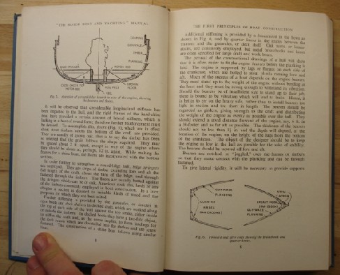
Fig. 5. A section of a round-bilge launch in way of the engine, showing the bearers and floors
Fig. 6. Forward and after-ends diagram showing the breast hook and quarter knees
Fig. 7a. Clinker or lap strake, planking
Fig. 7b. Carvel planking
Fig. 8. Double diagonal planking
Fig. 9. An illustration of seam batten planking
Fig. 10. Diagrams showing the terms commonly applied to the various parts of a motor cruiser, also to a hard-chine runabout planked on the seam batten principle
Fig. 11. A section of the deck showing the construction
Chapter 3. Hull Design
Part I - Displacement Boats
Fig. 12. Diagram showing the effect of over-driving on a small boat
Fig. 13. Diagram showing how redistribution of weight causes a change of
trim to keep the centre of buoyancy (C.B.) in line with the centre of gravity (C.G.)
Figures 14a) and 14b) - Power and speed graphs - a) curves showing reduction in power with
increases in length and b) effect of respacing sections to produce a longer or shorter hull
Figure 14(c). Power and speed graph for a boat of 30FT L.W.L & various displacements
(displacement in tons)
Fig. 15. Diagram and equations showing how midship, block and prismatic coefficients are determined
Fig. 16. Diagram - how a high centre of gravity causes instability
Fig. 17.
Diagram - convex and concave bow sections
Part II -
Planing Boats
Fig. 18. Comparison of powering for round-bilge and V-bottom hulls
-Round-bilge or Chine
Fig. 19. Diagram - Comparison of powering for round-bilge and V-bottom hulls
Fig. 20. Diagram - Cross-sections
showing variations on the hard chine hull form
-Displacement, Shape of Section and Beam
-The Planing Angle
Fig. 21. Resistance plotted against trim angle
-Stepped Hulls
Part III - Preparing the Drawings
-General Arrangement
-The Lines
Fig. 22.
Diagram - shows the lines of a 29ft. light draught motor cruiser designed by Peter Thornycroft
Fig. 23. Full page diagram showing the general arrangement of a 46-ft. motor yacht designed by John Bain. Side and upper elevation - no dimensions given
Chapter 4.
Practical Details of Boat Building
-The Moulds
-Setting up Moulds
Fig. 24. Diagram giving directions for setting up the moulds and for making the scarph joint between stem and keel
-Keel, Stem and Sternpost
-Timbering
-Planking
-Turning Over, Fitting Gunwales, etc.
-Floor Frames and Stringer
-Frames for a Hard-Chine Boat
-Engine Bearers
-Sternture Chock or Shaft Log
Fig. 25. Diagram - marking off the shaft line
-Deck, Thwarts, Seats, etc.
-Shaft Line-Boring
Fig. 26. Diagram of boring the stern tube check
-Woods used in boat construction
-Notes on the selection of timber
-Plywood in boatbuilding
-Painting and varnishing
Chapter 5.
High-Speed Motor Boats
All photographs referred to below are in black and white
-The Skimming Principle
Fig. 27. Diagram - a single-step hydroplane (left) at rest and (right) in running trim
-Limitations of Skimming Boats
-The World's Fastest Boats
Fig. 28. Photograph of "Slo-mo-shun IV," the American prop-riding hydroplane which set up a world record speed of 178.49 m.p.h. on July 7, 1952. Shows the boat lifted clear of the water within a boat shed
Fig. 29. Photograph - "Slo-mo-shun IV" in action
Fig. 30. A drawing of Sir Malcolm Campbell's original "Blue Bird," with a cutout showing how the machinery is installed within the boat
-"Crusader"
Fig. 31.
Photograph - The second "Blue Bird" as she was in 1939
Fig. 32. Photograph
- "Crusader" speeding at 173m.p.h on Loch Ness, September 19, 1952
Fig. 33. Large fold-out sectional drawing of John Cobb's Jet-Propelled 31-ft. boat "Crusader". Numbered diagram with legends
Fig. 34. Photograph - The Italian hydroplane "Massimo," which set up a world record for outboards of 83.473 m.p.h. in September, 1953
Fig. 35. Photograph of "Starlight," a Bates 29-ft fast cruiser
Fig. 36. Photograph of the Thornycroft fast launch "Sunga Marutham," built for the Ceylon Customs
Fig. 37. Photograph of a Taylor 22.5-knot launch built for the official use of the Governor of Nigeria
Fig. 38. Photograph of a 28-knot crash tender built by Vosper's for the R. A. F (Royal Air Force)
-Small high-speed boats
Chapter 6.
Plans and Building Instructions for Six Small Craft
(and yes - you could build these if you bought this book...). Rutland can be easily built by two friends or with the help of the family. Apart from the plans and timber, all that is needed is an ordinary set of carpenter's tools, the space for building and the ambition to own this inexpensive little ship
1. Rutland - a 16-ft. cabin cruiser
Fig. 39. Drawing showing the profile and general arrangement of Rutland
Fig. 40. The lines, body plan and offsets. Includes dimensions on the side elevation and heights and half breadths measurements in the table of offsets. The half beam pattern (with camber) and finished pattern are shown with dimensions
SPECIFICATIONS
-Layout description
-Instructions for building Rutland
Fig. 41. - general constructional details: three
top and side elevational plans with dimensions
Fig. 42. Stem assembly diagram with dimensions
Fig. 43. The boat frames, transom and sectional information with dimensions
Fig. 44. Erection of the centreline and transverse frames
Fig. 45. Diagrammatic instructions
for positioning the plywood planking
Fig. 46. Diagram of the cabin trunk and cockpit coamings
Fig. 47. A diagrammatic drawing of the mid-ship section and the steering gear arrangements
Fig. 48. Diagram of the installation, steering gear and main bulkhead details
Table of materials required: timber, fastenings, equipment (e.g. anchors, bilge pump, etc), paint
2. A 22-ft Cabin Cruiser
Fig. 49. General arrangement of the 22-footer
Fig. 50. Side elevation drawing
with dimensions of the lines of the 22-ft Cabin Cruiser
Table of offsets (sheer line, chine line, rabbet line, bottom of keel...)
Fig. 51. Drawing of the main centre framing set up with the transom and midship frame in position
Fig. 52. Diagram showing the stem and keel assembly with sections through various points
Fig. 53. Side and top elevation constructional drawing with dimensions
SPECIFICATION
3. a 24-ft. Vee-Bottom Cruiser
Fig. 54. Profile and plan of the 24-ft. cruiser
SPECIFICATION
Fig. 55. General arrangement and offsets. Side and top elevations with table of offsets
Fig. 56. The lines and sectional details
4. The Darby One-Design Hydroplane
Fig. 57. The profile, showing the position of the installation
Fig. 58. Side and top elevational drawings of the general arrangement and constructional details of the Darby hydroplane
SPECIFICATION
Fig. 59. Drawing showing the lines of the 12-ft. 6-in. Darby One-design hydroplane (showing dimensions)
Fig. 60. Diagram of the body plan
-Machinery
-Instructions for Step-by-Step Construction
Fig. 61. Diagram - How the frames are laid off
Fig. 62. Diagram - The first steps in setting the boat up
Fig. 63. Diagram - How to obtain the curve of the stem on the laying off board
Fig. 64. Diagram - Constructional details of the stem and step
Fig. 65. Diagram - The transom framework
Fig. 66. Diagram - An illustration, not to scale, of the special method of planking employed
Fig. 67. Diagram - Arrangement of the dashboard
Fig. 68. Diagram - the skeg, water intake and stern gear fittings
Fig. 69. Diagram - the engine mounting brackets
Fig. 70. Diagram - A cradle of simple construction
Table of offsets - actual size of frames
5. A 14-ft. 6-in. Cruising Launch
Fig. 71. Diagram - profile and sail plan of the 14-ft. 6-in. cruising launch
Table of offsets - all dimensions to inside of skin. All heights from the base line
Fig. 72. Diagram showing the general arrangement of
the cruising launch showing dimensions
Fig. 73. Full page diagram of the lines of the cruising launch with dimensions
6. A 16-ft. Fast Runabout
Fig. 74. Scale diagram - side and top elevation of the 16-ft. fast runabout, profile and plan
SPECIFICATION
Table of offsets
Fig. 75. Scale diagram showing the lines of the 16-footer
Fig. 76. Scale diagram showing the general arrangement of the fast runabout (side and overhead elevations)
Fig. 77. Scale diagram of the midship section looking forward
Fig. 78. Scale diagram giving directions for bevelling the stem
Chapter 7. Metal Hulls
Fig. 79. Photo of the light-metal ocean racer "Gulvain"
Fig. 80. Scale diagram showing the general arrangement plans of the "Morag Mhor"
-top and side elevations
Fig. 81. Photo of a Viking Marine 16-ft. alloy motor-dinghy
Fig. 82. Photo of the Albatross Marine sports runabout
-A 17ft. Outboard Motor Boat
Fig. 83. Photo of the "Tonquin," built of light metal by Grimston and Astor Ltd
Fig. 84. Diagrams showing constructional details of a light-metal launch for the amateur builder
Fig. 85. Plan of the light-metal 17-ft. launch
Steel Craft
Fig. 86. Photo of the de Vries Lentsch steel motor yacht "Jimax III."
Fig. 87. Photo of a 38-ft. steel motor launch built for Sir Alfred Beit for service on Lake Nyasa by Mechans Ltd. of Glasgow
Fig. 88. Scale diagram (top and side elevations) of the general arrangement of a 28-ft welded steel auxiliary
Chapter 8. Plastic Boats
Fig. 89. Scale diagram showing the general arrangement of the Halmatic 45-ft cruiser
Fig. 90. Photograph of the moulded hull of the Halmatic cruiser ready for fitting out
Fig. 91. Photograph of a boatbuilder's shed in the United States complete with a landing craft for the Navy Department ready for fitting out
Fig. 92. Photograph of a 24-ft motor cruiser of US construction
Fig. 92. A Tod 12-ft glass fibre speed boat capable of 25 m.p.h.
Fig. 94. A glass fibre 25-ft. fast launch made by Halmatic Ltd.
Fig. 95. Moulding and fitting out at Southampton Launch and Boat Co.
Chapter 9. Propellers and Propulsion Systems
-Propeller
characteristics
Fig. 96. Graph of boat speeds in knots plotted against propeller pitches and speeds, allowing for 20 per cent., 10 per cent and 30 per cent. slip. For speeds in statute miles per hour, multiply by 1.15. (for higher speeds, see Fig. 97.)
Fig. 97. Fold out chart of boat speeds in knots plotted against propeller pitches and speeds, allowing for 20, 10 and 30 per cent. slip. For speeds in statute miles per hour multiply by 1.15.
Fig. 98. Graph giving propeller diameters for speeds up to 3,000 r.p.m
-Selecting a propeller
-Measuring propeller pitch
-Calculating horsepower
Fig. 99. Diagram illustrating measurement of pitch
-Powers, speeds and propeller sizes
Table giving examples of propeller sizes
Fig. 100. Graph showing the approximate powers required to propel cruisers and motor yachts of the dimensions shown to various speeds, based on the results of actual trials. The dotted lines are determined from less extensive data than the solid lines
Table showing sizes of high-tensile bronze shaft required
-Reversing and Variable Pitch Propellers
Fig. 101. Diagram showing the blade positions of a reversing and feathering propeller (pitch angles are exaggerated)
Fig. 102. The Stanton reversing
propeller with its operating gear
-The Stanton Reversing Propeller
Fig. 103. A close-up view of the mechanism in the boss
-The S.P.M. Variable-Pitch Propeller
Fig. 104. Sectional drawing showing the general arrangement of an S.P.M. propeller with its operating gear and controls
-The Rotol Variable-Pitch Propeller
Fig. 105. Illustration of a Rotol variable-pitch propeller showing the mechanism in the boss
Fig. 106. Diagram showing the arrangement of a Rotol v.p. propeller and its operating gear
Fig. 107. Cutaway drawing of a Rotol oil transfer unit
-Propellers for Sailing Yachts
Fig. 108. A Bruntons folding propeller
-Bruntons Folding Propeller
-The P.N.P. Duerr Feathering Propeller
Fig. 109. Sectional drawing showing the arrangement of the P.N.P. Duerr self-feathering propeller, reversible type
Fig. 110. Cut-open sketch of a Hotchkiss cone propeller unit for small craft
Fig. 111. Scale diagram of the 55-ft. passenger motor vessel "Exonia" which is driven by Hotchkiss cone propellers. She has a speed of 9 knots with two h.p. Diesel engines. The draught with 150 passengers is only 24 in.
-Gill Hydraulic Jet Propulsion
Fig. 113. 3 diagrams showing the gill jet propulsion arrangements. 1. Pump unit with one deflector for adjusting the direction of the propulsive jet and another to direct the flow of water as required either for propulsion or for other purposes. 2. Propelling unit with pivoted deflector which is lowered to give a reverse thrust. 3. Propelling unit with screw-down deflector
-Airscrew Propulsion
Fig. 114. Photo of a Davies 28-ft. hydroglider with a draught of only 3.5 inches
-Above-water Jet Propulsion
Chapter 10. Transmission
-Gleniffer Reverse Gear
Fig. 115. Diagram showing a cross-section of a Gleniffer reverse gear
-The Parsons Reverse Gear
Fig. 116. A Parsons reverse gear suitable for transmitting 10 b.h.p. per 100 .pm. It is shown with reduction gear attached
-The Stuart Epicyclic Gear
Fig. 117. Diagram of the Stuart epicyclic reverse gear with single lever control
Fig. 117a. Diagram of a reduction gearbox for use with the Stuart reverse gear
-Bruce
and Holroyd Gear-and-Chain Box
Fig. 118. A Bruce and Holroyd reverse gear for powers up to 35 h.p. at 1,500 r.p.m.
Fig. 119. 3D Drawing showing the mechanism of an S.L.M. oil-operated reverse-reduction gear
-Oil-operated gearboxes-S.L.M. Constant-Mesh Type
Fig. 120. Photograph of an S.L.M. reverse-reduction gearbox opened up
-Epicyclic Box by Self-Changing Gears (Self-Changing Gears Ltd manufactured in Lythalls Lane, Coventry) and made a series of oil-operated gearboxes
Fig. 121. Drawing showing a section
through the oil-actuated gearbox, type MR8B, of Self-Changing Gears Ltd
-"Handed" Reduction Gears
-The Vee Drive
Fig. 122. Drawing of the B. and H. reduction gearbox with chain drive. It can also be supplied with gear drive, so that handed pairs are available
Fig. 123. Drawing of a vee-drive incorporating the reduction gear. The driving shaft above is connected to the engine; the tailshaft is below
-Transom Drive. A unit of this type employing
chain drive was made by the Coventry Victor Motor Co., Ltd., Coventry, England
Fig. 124. A Parsons sailing clutch with thrust bearing
Chapter 11. Installation
-Lining-up of engine and shafting
Fig. 125. An example of a reasonable shaft angle in an auxiliary installation
-Electrolytic Action
-The Sterntube
Fig. 126. Drawing of a typical sterntube assembly
Fig. 127. Photograph of the Stuart adjustable shaft log
-Propeller Brackets and Shaft
Fig. 128. Drawing showing how you could install a zinc ring to reduce electrolytic action on a steel tailshaft
Fig. 129. Drawing showing (left) a sectional elevation and plan of a propeller bracket and (right) an A-bracket
Fig. 130. Photograph of a water-lubricated tailshaft bearing made of the plastic material Tufnol
Fig. 131. Drawing illustrating cavitation due to a propeller bracket
-Protection of the Engine
Fig. 132. Diagram of a marine installation employing Silentbloc anti-vibration mountings and flexible couplings of a type able to take thrust
-Sound insulation
Fig. 133. An installation drawing for a twin-engined craft showing side, top and cross-sectional elevations
Fig. 134. Photo of
a well-appointed Thornycroft Diesel engine installation in a twin-screw customs launch
-Fuel Tanks and Connections
-Fuel Pipes
Fig. 135. Drawing of a cone union for piping
-S.B.B.N.F. Code of Practice For the Prevention of Accidents that made recommendations of minimum requirements for the
1.
Petrol Installation for Motor Fuel concerning tanks, petrol filler, piping, fittings and flanges, tanks, petrol pumps, gravity feed systems, flame traps, engine tray
2. Butane Gass Installations concerning installation, cylinder valves, all cylinders and regulating devices, securing of cylinders and equipment, piping, joints, bends, flexibility, control taps, avoidance of draughts, ventilation, insulation, pressure regulator, leakage test
3. General Constructional Recommendations concerning access, fire extinguishers, ventilation, insulation, batteries, electrical wiring
-Ignition Fittings
-Water piping
Fig. 136. Drawing of two forms of water intake
Fig. 137. The Thornycroft combined water inlet and clean-in service-type strainer
Fig. 138. Photograph
four Thornycroft external fresh water cooling units on a passenger vessel called Clifton Castle
-Exhaust Fittings
-A "Dry" Exhaust
-A "Wet" Exhaust
Fig. 139. Drawing of "Dry" exhaust arrangements
Fig. 140. Drawing showing the details of "wet" exhaust systems
Fig. 141. Drawing of the wheel steering easily disconnected to enable the tiller to be used
Fig. 142. Photograph of a neatly arranged control position
with comprehensive instrument panel, in a motor cruiser
Fig. 143. Photograph showing the control position of a Thornycroft launch, with cartype wheel, Mathway steering gear and Bloctube engine controls
-Engine Controls
Fig. 144. Photograph showing the controls of a Bates Star Craft cruiser, with horizontal reverse-gear levers
Fig. 145. Drawing showing the arrangement of the Thornycroft inter-connected reverse gear and engine speed control
Fig. 146. Drawing showing the gearbox unit (left) and throttle control cylinder of the Sequent single-lever device
Fig. 147. A neat, compact set of Trianco remote control transmitters for a triple-screw craft
Fig. 148. Cross-sectional drawing of the Exactor throttle control
-Ventilation
Fig. 149. The Manners Telealarm warning device
Fig. 150. Drawing of the Revon cowl ventilator, supplied by W.M. Still and Sons, Ltd., showing the water-excluding arrangement
Fig. 151. Drawings of 1. A cast half cowl ventilator - a space saver, but not adjustable; 2. The Clyde ventilator which gives either up-cast of downcast draught; 3. A tilting-top mushroom ventilator; 4. A butterfly type bulkhead vent. All these were supplied by Simpson Lawrence Ltd
-Fire-Extinguishing Appliances
Fig. 152. Two of the airmax electrically-driven screw fans, supplied by A.K. Fans, Ltd. The fan on the right of the two fans illustrated, which was a bilge ventilating fan, had passed official flameproof tests
Fig. 153. Drawing, with cross-sectional view, of a CO2 (carbon dioxide) fire-extinguishing installation with remote control in a motor cruiser; it was made by the Pyrene Co., Ltd, makers of all types of fire-fighting equipment
-Auxiliary Machinery
Chapter 12.
Electrical Equipment for Boats
-Dynamos
-Batteries and Battery Charging
Fig. 154. Circuit diagram for taper charging
-Distribution
Fig. 155. Correct arrangement of a watertight deck socket
Fig. 156. Diagram of a watertight bulkhead gland shown assembled but not tightened
-Radio Interference Suppression
-Lightning Conductors
-Examples of Actual Installations
Fig. 157.
Diagram of a comprehensive 24-volt electrical system installed in a 46ft motor sailer
Fig. 158. Diagram of a 6-volt system for a 10-ton auxiliary
-Care and maintenance
Fig. 159. Diagram of a 12-volt system with shore-charged battery, for a 10-tonner
Fig. 160. A 500-watt, 25 volt Stuart auxiliary generating set, with bilge and general service pump
Chapter 13. Petrol and Vaporizing Oil Engines
-Current British Models
[as of 1954]
Fig. 161. The 4 h.p. Brit Minor
-Aquaplane: The Aquaplane Co., Oulton Broad, near Lowestoft
Table of B.h.p., R.p.m., No of Cylinders, Bore (inches), Stroke (inches), Weight (lb) and Price [as of 1954!] for the Aquaplane Racing 39 and Racing 45 engines (converted Ford Ten engines, specially tuned for racing)
-Austin: Austin Motor Co., Ltd., Longbridge Works, Birmingham
Table of B.h.p., R.p.m., No of Cylinders, Bore (inches), Stroke (inches), Weight (lb) and Price [as of 1954!] for the Skipper 35, Skipper 60, Skipper 100, Chief 10, Chief 25 and Chief 40 engines
-Brit: Brit Engineering Co., Ltd., Bridport, Dorset.
Table of B.h.p., R.p.m., No of Cylinders, Bore (inches), Stroke (inches), Weight (lb) and Price [as of 1954!] for the Minor, A, D, E, E/10, F, F/20, L, M engines; and Vaporizing Oil engines: D, E, E/10, F, F/20, L and M
Fig. 162. A Coventry Victor opposed four-cylinder Neptune petrol engine with reverse-reduction gear
Fig. 163. The 30h.p. Kelvin Ricardo, petrol-vaporizing oil engine model F.4.
-Coventry Victor: The Coventry Victor Motor Co., Ltd., Cox Street, Coventry
Table of B.h.p., R.p.m., No of Cylinders, Bore (inches), Stroke (inches), Weight (lb) and Price [as of 1954!] for the Midget M.W.1, Midget M.W.2., Type N (Mk.2) W.N.2., Type N (Mk.2) W.N.3, Type N (Mk.2) W.N.4, Neptune W.C.2, Neptune W.C.3, and Neptune W.C.4 engines (all horizontally opposed engines. The type N and the Neptune engines were all available in vaporizing oil variants
-Feltham: Bruce and Holdroyd, Ltd., 86 High Street, Feltham, Middlesex
Table of B.h.p., R.p.m., No of Cylinders, Bore (inches), Stroke (inches), Weight (lb) and Price [as of 1954!] for the S.M.1 and T.M.1 engines (suitable for petrol or vaporizing oil)
Fig. 164. Sectional drawing of the 14-38 h.p. Meadows Kingfisher petrol engine with reduction gear and on the right a section through the reverse gearbox
Fig. 165. Photograph of a handed pair of Meadows Kingfishers
-Kelvin Poppet Valve: The Bergius Co., Ltd., 254 Dobbie's Loan, Glasgow, C.4.
Table of B.h.p., R.p.m., No of Cylinders, Bore (inches), Stroke (inches), Weight (lb) and Price [as of 1954!] for the 3.5 in.-2; 3.5 in.-4; 5.5 in.-2; 5.5 in.-4
-Kelvin Ricardo: The Bergius Co., Ltd., 254 Dobbie's Loan, Glasgow, C.4.
Table of B.h.p., R.p.m., No of Cylinders, Bore (inches), Stroke (inches), Weight (lb) and Price [as of 1954!] for the E.2; E.4; F.2; and F.4 engines
-Meadows: Henry Meadows, Ltd., Fallings Park, Wolverhampton
Table of B.h.p., R.p.m., No of Cylinders, Bore (inches), Stroke (inches), Weight (lb) and Price [as of 1954!] for the Kittiwake 8-28; and Kingfisher R.S.1 engines
Fig. 166. Photograph of the 33-63 h.p. Morris Commodore Mark III petrol engine with reduction gear
-Morris: Morris Motors, Ltd., Cowley Oxford
Table of B.h.p., R.p.m., No of Cylinders, Bore (inches), Stroke (inches), Weight (lb) and Price [as of 1954!] for the Vedette Mk. IV; Navigator Mk. II; Commodore Mk. III
Fig. 167. Photograph of the 8 h.p. Stuart petrol engine, model P55ME
Fig. 168. Cross-sectional drawing through the Vosper V8 petrol engine
-Norman: Norman Engineering Co. Ltd., Millers Road, Warwick
Table of B.h.p., R.p.m., No of Cylinders, Bore (inches), Stroke (inches), Weight (lb) and Price [as of 1954!] for the T.300 Mk. II and T.600 Mk. 1 air-cooled engines
-Parsons: Parsons Engineering Co., Ltd., Town Quay, Southampton
Table of B.h.p., R.p.m., No of Cylinders, Bore (inches), Stroke (inches), Weight (lb) and Price [as of 1954!] for the Prawn, Pike Petrol, Perch and Pike Kerosene engines (marine versions of Ford engines)
-Stuart: Stuart Turner, Ltd., Market Place, Henley-on-Thames, Oxfordshire
Table of B.h.p., R.p.m., No of Cylinders, Bore (inches), Stroke (inches), Weight (lb) and Price [as of 1954!] for the R3MC, R3M, P5MC, P5M, P5MR, P5ME, P5MRE, P55MC, P55M, P55MR, P55ME, P55MRE and P55MRT two-stroke engines. Engines ending in C have no reverse gear; electric starting models end in E. Models ending in R include reduction gear
-Vosper: V-8 Vosper, Ltd., Portsmouth
Table of B.h.p., R.p.m., No of Cylinders, Bore (inches), Stroke (inches), Weight (lb) and Price [as of 1954!] for the V-8 engine, a marine conversion of the Ford V-8
-Watermota: Watermota Marine Engines, Ltd., Newton Abbot, South Devon
Table of B.h.p., R.p.m., No of Cylinders, Bore (inches), Stroke (inches), Weight (lb) and Price [as of 1954!] for the K1, K2 and C4 engines. K1 and K2 were two-stroke units; C4 was four-stroke based on the Ford 10
Chapter 14. Diesel Engines
Fig. 169. Three diagrams illustrating three diesel engine combusion chamber arrangements. Top left: Ruston, direct injection with dished piston crowns; Top Right: Gleniffer, clerestory chamber with horizontally-opposed valves; and Left: Perkins, a combination of direct and indirect injection
Current British Models [as of 1954]
Fig. 170. Part-sectioned drawing of a C.A.V. fuel injection pump for a six cylinder engine with variable speed weight-type governor and plunger feed pump
-A.E.C.: AEC., Ltd., Southall, Middlesex
Table of B.h.p., R.p.m., No of Cylinders, Bore (inches), Stroke (inches), Weight (lb) and Price [as of 1954!] for the A209 and A210 engines
Fig. 171. Drawing of a section through
a C.A.V. diesel engine injector
Fig. 172. Photograph of a handed pair of A.E.C. 100 h.p. diesel engines
-Ailsa Craig: Ailsa Craig, Ltd., Ashford Kent
Table of B.h.p., R.p.m., No of Cylinders, Bore (inches), Stroke (inches), Weight (lb) and Price [as of 1954!] for the RF1, RF2, RF3, RF4, and RF6 engines
Fig. 173. Illustration of a section through the cylinder head of an A.E.C. diesel engine, showing the A.E.C.-Ricardo Comet Mark III* combusion chamber design
-Albion Albatross: Warwick Motor Engineering Co., Ltd., Copeland Street, Stoke-on-Trent Table of B.h.p., R.p.m., No of Cylinders, Bore (inches), Stroke (inches), Weight (lb) and Price [as of 1954!] for the Albion Albatross
-BRIT: Brit Engineering Co., Ltd., Bridport, Dorset
Table of B.h.p., R.p.m., No of Cylinders, Bore (inches), Stroke (inches), Weight (lb) and Price [as of 1954!] for the LJ/2 and LJ/2R
Fig. 174. Illustration of an air-cooled diesel engine, the 15 h.p. two-cylinder Enfield
-British Polar: British Polar Engines, Ltd., 161 Helen Street, Glasgow, S.W.1.
Table of B.h.p., R.p.m., No of Cylinders, Bore (inches), Stroke (inches), Weight (lb) and Price [as of 1954!] for the M44E, M45E, M46E, K43E, K44E and K45E. All are 2 stroke units
-David Brown: David Brown Tractors (Engineering), Ltd., Meltham, Yorkshire
Table of B.h.p., R.p.m., No of Cylinders, Bore (inches), Stroke (inches), Weight (lb) and Price [as of 1954!] for the MD4 engine
-Coventry Victor: The Coventry Victor Motor Co., Ltd., Cox Street, Coventry
Table of B.h.p., R.p.m., No of Cylinders, Bore (inches), Stroke (inches), Weight (lb) and Price [as of 1954!] for the W.D.1, W.D.2 and the W.D.3 engines
-Crossley: Crossley Brothers, Ltd., Openshaw, Manchester, 11
Table of B.h.p., R.p.m., No of Cylinders, Bore (inches), Stroke (inches), Weight (lb) and Price [as of 1954!] for the BWM2/8, BWM2/9, BWM2/10, BWM2/11, BWM2/12, BWM3/8, BWM 3/9, BWM3/10, BWM3/11, BWM4/8, BWM3/12, BWM4/9, BWM3/13, BWM4/10, BWM5/8, BWM4/11, BWM5/9, BWM4/12, BWM5/10, BWM6/8, BWM4/13, BWM6/9, BWM5/11, BWM5/12, BWM6/10, BWM5/13, BWM6/11, BWM5/15, BWM6/12, BWM6/13, BWM6/15, ERL3/45, ERL3/50, ERL3/60, ERL4/45, ERL4/50, ERL5/45, ERL4/60, ERL5/50, ERL6/45, ERL4/75, ERL5/60, ERL6/50, ERL6/60, ERN8/45, ERL5/75, ERL8/50, ERL6/75. All the ERL series and ERN8/45 series are two-stroke units
Fig. 175. Illustration of a longitudinal and cross-section through the Foden 105-120 h.p. six-cylinder two-stroke diesel engine
-Dorman: W.H. Dorman and Co., Ltd., Stafford
Table of B.h.p., R.p.m., No of Cylinders, Bore (inches), Stroke (inches), Weight (lb) and Price [as of 1954!] for the 3DLMIII, 4DLMIII, and 6DLMIII engines
Fig. 176.
Illustration of a handed pair of Gardner 8L3 diesel engines: they develop 152 h.p. each at 900 r.p.m
-Enfield: Enfield Industrial Engines Co., Hewell Road, Redditch, Worcestershire
Table of B.h.p., R.p.m., No of Cylinders, Bore (inches), Stroke (inches), Weight (lb) and Price [as of 1954!] for the M.V.S.1 and M.H.O.2 engines
-English Electric: The English Electric Co., Ltd, Marine Department, Willans Works, Rugby
Table of B.h.p., R.p.m., No of Cylinders, Bore (inches), Stroke (inches), Weight (lb) and Price [as of 1954!] for the 4RKM engine
-Foden: Fodens Ltd., Elworth Works, Sandbach, Cheshire
Table of B.h.p., R.p.m., No of Cylinders, Bore (inches), Stroke (inches), Weight (lb) and Price [as of 1954!] for the FD4, FD6 and FD12 engines (all two stroke with direct injection)
-Gardner: Norris, Henty and Gardners, Ltd., Patricroft, Manchester
Table of B.h.p., R.p.m., No of Cylinders, Bore (inches), Stroke (inches), Weight (lb) and Price [as of 1954!] for the 2LW, 3LW and 4LW heavy and light duty engines, 4LW high speed, 5LW heavy and light duty and high speed, 6LW heavy and light duty and high speed, 3L3, 4L3, 5L3, 6L3, 8L3
-Gleniffer Engines, Ltd., Anniesland, Glasgow, W.3.
Table of B.h.p., R.p.m., No of Cylinders, Bore (inches), Stroke (inches), Weight (lb) and Price [as of 1954!] for the DB2, DB3, DB4, DB6, DH3, DH4, DH6, DH8
Fig. 177. The Gleniffer 120 h.p: DH6 diesel engine
-Godiva: Coventry Diesel Engines, Ltd., Friars Road, Coventry, Warwickshire
Table of B.h.p., R.p.m., No of Cylinders, Bore (inches), Stroke (inches), Weight (lb) and Price [as of 1954!] for the CD2, CD4 and KF4 engines
-Kelvin Diesel: The Bergius Co., Ltd., 254 Dobbie's Loan, Glasgow, C.4
Table of B.h.p., R.p.m., No of Cylinders, Bore (inches), Stroke (inches), Weight (lb) and Price [as of 1954!] for the J.2, J.3, J.4, K.2, K.3, K.4, *KR4, *KR6, L.2, L.3, L.4, *LR4, and *LR6 engines
-Lister: R. A. Lister (Marine Sales), Ltd., Dursley, Gloucestershire
Table of B.h.p., R.p.m., No of Cylinders, Bore (inches), Stroke (inches), Weight (lb) and Price [as of 1954!] for the *AD, FRM 1, FRM 2, FRM 3, FRM, 4, and FRM6
-McLaren: J. and H. McLaren, Ltd., Airedale Works, Hunslet, Leeds 10
Table of B.h.p., R.p.m., No of Cylinders, Bore (inches), Stroke (inches), Weight (lb) and Price [as of 1954!] for the M2, M3, M4, M5, M6 and M8 engines
-Meadows: Henry Meadows, Ltd., Fallings Park, Wolverhampton
Table of B.h.p., R.p.m., No of Cylinders, Bore (inches), Stroke (inches), Weight (lb) and Price [as of 1954!] for the 4DM330, 4DM420, 6DM630, 6DM970 and 6DMS970 engines
-Mirrlees: Mirrlees, Bickerton and Day, Ltd., Hazel Grove, near Stockport, Cheshire
Table of B.h.p., R.p.m., No of Cylinders, Bore (inches), Stroke (inches), Weight (lb) and Price [as of 1954!] for the JGMR3, JGMR4, and JGMR5 engines
-Morris: Morris Motors, Ltd., Cowley, Oxford
Table of B.h.p., R.p.m., No of Cylinders, Bore (inches), Stroke (inches), Weight (lb) and Price [as of 1954!] for the Sea Lord engine
-National: The National Gas and Oil Engine Co., Ltd., Wellington Works, Ashton-under-Lyme, Lancashire
Table of B.h.p., R.p.m., No of Cylinders, Bore (inches), Stroke (inches), Weight (lb) and Price [as of 1954!] for the M4AM3, M4AM4, M4AM5, M4AM6, M4AM7, M4AM8, *M4AUM6, *M4AUM8, R4AM5, and R4AM6 engines. *=pressure charged
-Parsons: Parsons Engineering Co., Ltd., Town Quay, Southampton
Table of B.h.p., R.p.m., No of Cylinders, Bore (inches), Stroke (inches), Weight (lb) and Price [as of 1954!] for the Pike Diesel, a marine version of the Ford Tractor Diesel Engine
Fig. 178. Sectional drawing of the Perkins 27-43 h.p. P4M Diesel engine with reduction gear
-Pelapone-Ricardo: Pelapone Engines, Ltd., Slack Lane, Derby
Table of B.h.p., R.p.m., No of Cylinders, Bore (inches), Stroke (inches), Weight (lb) and Price [as of 1954!] for the 52, 53, 54, and 56 engines
-Perkins: F. Perkins Ltd., Peterborough, Northants
Table of B.h.p., R.p.m., No of Cylinders, Bore (inches), Stroke (inches), Weight (lb) and Price [as of 1954!] for the P4M, P6M and S6M engines
-Petter: Petters, Ltd., Causeway Works, Staines, Middlesex
Table of B.h.p., R.p.m., No of Cylinders, Bore (inches), Stroke (inches), Weight (lb) and Price [as of 1954!] for the AV2M, B2M, B3M and B4M engines
-Rolls-Royce: Rolls-Royce, Ltd., Derby
Table of B.h.p., R.p.m., No of Cylinders, Bore (inches), Stroke (inches), Weight (lb) and Price [as of 1954!] for the C4 unsupercharged, C4 supercharged, C6 unsupercharged, C6 supercharged and C8 unsupercharged engines
Fig.
179. The Perkins 47-65 h.p. P6M diesel engine with oil-operated reverse gear and 2-1 reduction
Fig. 180. Cross-section of the Petter 10 h.p. diesel engine: direct injection is employed into a cavity in the piston top
-Russell Newbery: Russell Newbery and Co., Ltd., Essex Works, Dagenham, Essex
Table of B.h.p., R.p.m., No of Cylinders, Bore (inches), Stroke (inches), Weight (lb) and Price [as of 1954!] for the DM2, DM3, DM4, PDM4, EM3, EM4, and EM6 engines
-Ruston: Ruston and Hornsby, Ltd., Lincoln
Table of B.h.p., R.p.m., No of Cylinders, Bore (inches), Stroke (inches), Weight (lb) and Price [as of 1954!] for the 2VSHM, 3VSHM, 3VRHM, 4VRHM, 4YEM, 5YEM, 6YEM, 4VCBM, 5VCBM, 6VCBM, 4VEBM, 5VEBM, 4RPHM-II, V6RPHM-I, and V6RPHXM-I
-Stuart: Stuart Turner, Ltd., Market Place, Henley-on-Thames, Oxfordshire
Table of B.h.p., R.p.m., No of Cylinders, Bore (inches), Stroke (inches), Weight (lb) and Price [as of 1954!] for the H2M and H2MR engines - loop scavenged two-stroke engines
Fig. 181. Illustration of a Ruston two-cylinder Diesel engine Mark 2VSHM: it develops 22.5 h.p. at 1,500 r.p.m.
Fig. 182. The Stuart 9 h.p. Diesel engine, a two-cylinder, loop scavenged two-stroke. Drawing shows a longitudinal section through engine and gearbox, showing both reduction gear and direct drive arrangements. Inset: a section through the blower
Fig. 183. Photo of a Thornycroft RTR6 Diesel engine, which develops 50 h.p. at 1,900 r.p.m.; it is shown with oil-operated reverse gear and 3-1 reduction gear
-Thornycroft: Transport Equipment (Thornycroft) Ltd., Thornycroft House, Smith Square, London, SW1. Export sales: John I. Thornycroft and Co., Ltd (same address)
Table of B.h.p., R.p.m., No of Cylinders, Bore (inches), Stroke (inches), Weight (lb) and Price [as of 1954!] for the RJ2/1, RTR/4, RTR/6, RNR/6, and RZ/6 engines
-Turner Diesel: Turner Manufacturing Co., Ltd., Wulfruna Works, Villiers Street, Wolverhampton
Table of B.h.p., R.p.m., No of Cylinders, Bore (inches), Stroke (inches), Weight (lb) and Price [as of 1954!] for the IV95, 2V95, 4V95, 2L, 3L, 4VL, and 6VL engines
-Widdop: H. Widdop and Co., Ltd., Greengate, Keighley, Yorks
Table of B.h.p., R.p.m., No of Cylinders, Bore (inches), Stroke (inches), Weight (lb) and Price [as of 1954!] for the EMX, EMXT, EMX3, EMX4, EMX5, EMX6, EMB4, EMB5 and EMB6 engines
Chapter 15.
The Marine Gas Turbine
Fig. 184. Photograph of M.G.B. 2009 in 1947, the first naval vessel to be propelled by gas turbine machinery
Fig. 185. Photograph of H.M.S. "Bold Pioneer", P5701, moving at speed in 1953, driven by a pair of 4,500 h.p. gas turbines
Fig. 186. Drawing of the basic arrangement of the Rover gas turbine as installed in "Torquil"
Fig. 187. The Motor Boat and Yachting Manual artist's drawing of the engine installation in the 60-ft. launch "Torquil"; consisting of two Rover gas turbines as main propelling units and a Dorman Diesel piston engine as auxiliary. The diagram is labelled, showing parts from 1. Starter Motor to 31. Ventilating intake fans
Chapter 16. Outboard Motors and Boats
-General Principles
Fig. 188. The Motor Boat and Yachting Manual artist's perspective sectional drawing of the British Anzani 1.5h.p. Pilot outboard motor; it is surrounded by a steering ring instead of having the customary straight tiller arm. The drawing labels many of the parts in the motor - from flexible pump impeller to the tubular ring tiller
-Direct Drive Motors
Fig. 189.
Drawing of an air-cooled direct-drive unit, the 1.2h.p. Atco Boatimpeller, type 147
-Racing Engines
Current British Models
-Aquajet: Kenneth Long and Co: Ltd., 27-30 Basinghall Street, London, E.C.2.
Table of B.h.p., R.p.m., No of Cylinders, Bore (inches), Stroke (inches), Weight (lb), Shaft Length (in.) and Price [as of 1954!] for the Mk. IV engine
-ATCO Boatimpeller: Charles H. Pugh, Ltd., Atco Works, Birmingham, 9
Table of B.h.p., R.p.m., No of Cylinders, Bore (inches), Stroke (inches), Weight (lb) and Price [as of 1954!] for the 79 & 147 engines (direct-drive motors with air cooling)
-British Anzani: British Anzani Engineering Co., Ltd., Windmill Road, Hampton Hill, Middlesex.
Table of B.h.p., R.p.m., No of Cylinders, Bore (inches), Stroke (inches), Weight (lb) and Price [as of 1954!] for the Minor, Pilot, Super Single, Unitwin 10 and Unitwin engines
-British Seagull: British Seagull Co., Ltd., The Quay, Poole, Dorset
Table of B.h.p., R.p.m., No of Cylinders, Bore (inches), Stroke (inches), Weight (lb) and Price [as of 1954!] for the Little 40, Super 40 Plus, Fixed Drive 102 and 102 plus engines
-Brockhouse: Brockhouse Engineering (Southport), Ltd., Rufford Road, Crossens, Southport, Lancashire
Table of B.h.p., R.p.m., No of Cylinders, Bore (inches), Stroke (inches), Weight (lb) and Price [as of 1954!] for the Britannia and Swordfish engines
-Coventry Victor: The Coventry Victor Motor Co., Ltd., Cox Street, Coventry
Table of B.h.p., R.p.m., No of Cylinders, Bore (inches), Stroke (inches), Weight (lb) and Price [as of 1954!] for the Super-Speed S.S.6 2.5-6; and Super-Speed S.S.8 3.5-8 engines
Fig 190. Drawing of a powerful outboard motor, the 15.h.p. British Anzani Unitwin
-Ferrier: Kenneth Long and Co., Ltd., 27-30 Basinghall Street, London, E.C.2
Table of B.h.p., R.p.m., No of Cylinders, Bore (inches), Stroke (inches), Weight (lb) and Price [as of 1954!] for the 120 and Cormorant engines
-Harbormaster: Harbormaster, Ltd., Industrial Estate East, Harlow, Essex
Table of B.h.p., R.p.m., No of Cylinders, Bore (inches), Stroke (inches), Weight (lb) and Price [as of 1954!] for the 60 H/MR and 130 H/D engines
Fig. 191. The British Seagull 3.5 - 5 h.p. 102 Plus outboard motor, with long-range fuel tanks; it is unusual in having a four-bladed propeller
-Mallard: C. H. Haley and Co., Shaftesbury Road, Leicester
Table of B.h.p., R.p.m., No of Cylinders, Bore (inches), Stroke (inches), Weight (lb) and Price [as of 1954!] for the Mallard engine
-Viking: Southend Engineeing Co., Ltd., High Street, Leigh-on-Sea
Table of B.h.p., R.p.m., No of Cylinders, Bore (inches), Stroke (inches), Weight (lb) and Price [as of 1954!] for the Viking Cluth Model
-Installing the Engine
Fig. 192. Various types of mountings for outboard motors
a) - m)
-Yachts Tenders
Fig. 193. Photograph of the Duckling 9-ft. utility outboard dinghy, a product of Fairey Marine, Ltd
-A Speed Dinghy
Fig. 194. Photograph of The Phantom Four at speed; a speed dinghy built by Freebody's (Boat Builders), Ltd.
-A 20-ft. Utility Outboard Launch
Fig. 195. Side, top and cross-sectional scale diagram of the general arrangement of a 20-ft. utility outboard launch
Fig. 196. Side, top and cross-sectional scale diagram of the lines of a 20-ft. utility outboard launch
Fig. 197. Table of offsets of a 20-ft utility outboard launch in feet, inches and eighths
Fig. 198. General arrangement of the Wright ouboard runabout
-Racing Runabout
Fig. 199. Scale diagram of the British Outboard Racing Club's C50 hydroplane showing side and top elevations
Fig. 200.
Side, top and cross-sectional scale diagram of the constructional details of the A and B Class outboard hydroplane sponsored by the Southern Hydroplane Club
-Class C Racing Hull for Home Construction
-Hydroplane for Classes A and B
Fig. 201. Plan and elevational scale
drawing of a trailer for outboard boats
Fig. 202. Constructional details of the chassis and boat mountings
-American Hydroplane Design
-A Trailer for Outboard Boats
Chapter 17.
Motor Boat Racing and Records
Fig. 203. Photo of Alan Darby of the Lowestoft and Oulton Broad Motor Boat Club, one of the most successful of British outboard racing drivers, driving his B Class hydroplane "Wicky I".
Fig. 204.
Photo of a "Pits" scene with all the outboard motor boat race participants lined up in their boats at the outboard race meeting on Salford Reservoir, Birmingham
Fig. 205. Photo of V. L. Parry, of the Midlands Hydroplane Club, making a tight turn
Fig. 206. Photo of H. L. G. Melly, in his X Class hydroplane "Thunderbolt", winning "The Motor Boat and Yachting" Trophy in 1953
Fig. 207. Photograph of the Swedish driver Marcus Claesson (right) winning the C Class European Championship in Milan, 1953. His engine was an adapted J. A. P. unit
Fig. 208. Photograph entitled 'Scratch and Limit' - C. E. Sutton's "Rooster", a prop-riding hydroplane lapping the limit boat during the 1953 race on Oulton Broad for the Battle of Britian Trophy, which she won
At the end of the chapter is a table of the Unlimited Class World Speed Records from 1928 - 1952
Chapter 18. The Legal Side of Motor Boating
-Yachts on Charter
-Tonnage
Fig. 209. Graph of Thames tonnage at a glance - tonnage plotted agains length in feet (b.p.)
-Registering a Yacht
-Buying and Selling
-Changing a Yacht's Name
-Harbour Dues
-Registration on Thames and Broads
-Insurance
-Mortgage and Hire-Purchase
-The Crew
-Flags
-Wireless on Yachts
-Foreign Cruising
-Cruising on the French Inland Waterways
-Other European Waterways
-Quarantine Regulations
-Fare-Paying Passengers
-Rights of Navigation
Chapter 19. Hints on Handling a Motor Boat
-The Turning Effect of the Propeller
-Picking Up the Buoy
-Approaching and Leaving a Quay
Fig. 210. Simple diagram of a boat approaching a quay, accompanying the text for illustration of the points being made
Fig. 211. Diagram of how to get your boat clear in a narrow harbour showing direction of tide
-Manoeuvring in a Narrow Space
-Springs
Fig. 212. Diagram of springing in the bow or stern
-Anchoring
Fig. 213. Diagram of berthing between other vessels
Fig. 214. Diagram of the right (a) and wrong (b) method of laying two anchors
-Anchor Weights with table of Thames Tonnage, Bower Anchor weight (lb), diameter of chain (in.) and length of chain in fathoms
Chapter 20. Sailing and Sail Plans
-Various Rigs
Fig. 215. Drawing of a 31-ft. ketch with (left) Bermudan rig and (right) with gaff mainsail and
Bermudan mizzen (with measurements)
Fig. 216. Drawing of a sail plan of a 22-ft centreboard sloop designed by the late Eric H. French, A.M.I.N.A (with measurements)
Fig. 217. Drawing of the Thornycroft ketch-rigged motor sailer "Fidalga III"
-Ketch and Yawl Rigs
Fig. 218. Drawing of a 37-ft sloop-rigged motor cruiser designed by W. G. McBryde, M.I.N.A (with measurements)
Fig. 219. Drawing of the twin-hulled catamaran "Ebb and Flo," provided with a double sloop rig
-Sail Plan for a Lifeboat Conversion (with measurements)
-Learning to Sail a Dinghy
Fig. 220. Drawing of a sail plan for a 27-ft lifeboat conversion (with measurements)
Fig. 221. Drawing - a centreboard dinghy with standing lug sail and jib
-Tacking
Fig. 222. Drawing - plan of rigging details of a 13-ft dinghy (with measurements)
Fig. 223. Drawing showing the procedure of tacking
-Squalls
-Gybing
Fig. 224. Drawing showing gybing to change course with the wind aft
-Handling Larger Craft
-Sailing in Rough Weather
-Meeting a Head Sea
Chapter 21. Navigating Gear for the Cruising Yachtsman
Fig. 225. Illustration of a Sestrel Moor compass specifically designed by Henry Browne and Son, Ltd., for yachts with tiller steering
Fig. 226. Photo of a compass designed by Kelvin Hughes for motor and sailing yachts
-Radio Aids to Navigation
Fig. 227. Photo of the Kelvin Hughes echo sounder
Fig. 228. Photo of a Beme-Loop radio direction installation on the deck of a yacht
Fig. 229. Photo of the Pye Dolphin ship to shore radio telephone equipment
Fig. 230. Photograph of a Marconi radar display unit in the wheelhouse of the concern's research motor vessel "Electra II."
Chapter 22.
Boat Building Members of the Ship and Boat Builders' National Federation
Yachting and Motor Boat Clubs (as of 1954) split into regions from Berkshire to Yorkshire
Chapter 23. Yacht and Motor Boat Clubs split into regional groups from Thames and Estuary to South of England to Trade Associations
Index
Adverts:
-Thornycroft: boat-builder and diesel marine engine supplier
-Brunton's Propellers and Sterngear
-British Anzani advertising their super outboard motors: Unitwin, Super Single, Pilot, and the Minor
-Brit Engineering advertising the Brit Minor, Type E/10, Type F20, Type M and LJ/2
-Gleniffer advertising their marine diesels (the DH4 is shown)
-British Seagull: outboard motor
-RFI advertising their R.F.D. Rubber Dinghies and Lifejackets
-Industrial Unit's advert for marine conversions of their Industrial Diesel Engine for powering Fishing Vessels, Police Launches and Cabin Cruisers
-Kenneth M. Gibbs' full page advert of their yacht and boat-building services
-J. Samuel White of the Isle of Wight advertising their skills at building lifeboats, high speed craft, launches, fishing vessels, yachts and shallow draft vessels with a picture of a 38 ft. Motor Cruiser they built as a fishing boat, shown at Cockenzie
-Jubilee of Gillingham, Kent: screw-tightened metal clips
-The Bergius Company Ltd of Glasgow: their Kelvin marine engines with an illustration of their -Kelvin-Ricardo model E4 Petrol/Paraffin engine
-Donald V. Hotchkiss, Naval Architect: The Hotchkiss Cone Propeller
-The Navigators and General Insurance Co., Ltd., : advertising Motor Boat Insurance
-Vosper Ltd. of Portsmouth: advertised their shipbuilding skills in high speed craft, e.g. a 40ft Royal Barge, a 46ft. Crash Tender, a 28ft Fast Motor Launch, and for the Navy, H.M.S. Gay Bomardier "Gay" Class M.T.B.
-Pye's Dolphin Radio Telephone
-Camper and Nicholson: Ship and Yacht Builders showing a photo of the Twin Screw Motor Yacht "Loraymo IV" ex-"Brinmaric", built at Gosport in 1938 and modernised 1954 at Southampton
-Meadow's Marine Petrol and Diesel Engines - showing photos of 1. Porpoise Marine Diesel 60 S.H.P at 1800 R.P.M.; 2. Kittiwake Petrol Engine 28 H.P. at 3000 R.P.M.; 3. Kingfisher Petrol Engine 35 H.P. at 3000 R.P.M.; 4. Frobisher 6DM630 Marine Diesel 100 S.H.P. at 16.50 R.P.M
-Sherman's Supply Co: Specialists in Marine Equipment
-Gaines Propellers Up to 48 ins.
-C.A.V. Limited - manufacturers of fuel injection pumps with the 'N' Type shown on the advert
-Lodge spark plugs, Rugby
-British Twin Disc & Clarifiers' Marine Reverse and Reduction Gears
-Norris, Henty and Gardners, Ltd., of Patricroft Manchester's advert for Gardner's Marine Propulsion Oil Engines. The advert shows the 4L3 Engine with Unit Construction Reversing-Reducing Gear and below that a table of the engines Gardner makes with the ratings (B.H.P and R.P.M.) for Heavy Duty Commercial Operation, Ratings for Pleasure Craft and Similar Vessels; and finally Ratings for Special High Speed Craft
-Danforth Anchors
-Coventry Timber Bending Co., Ltd.: advertising their laminated timber products
-Wortham Black & Co. Ltd. - the Fisherboy Engine based on the Ford "10" Industrial Unit
-A. Rutherford & Co., Neptune Works, Birkenhead - shipbuilders and outfitters
-Bloctube Controls Limited: remote controls
-Parsons Engineering Co., Ltd., Southampton - the Pike Marine Diesel (shown on the advert)
-A. B. Savin-Taylor & Co., Naval Architects, Surveyors and Consultants for Commercial and Pleasure Craft
-Beme Electronic and Marine Equipments Ltd: The Beme-Loop Mk. II a radio and D/F instrument for yachts
-The Motor Boat and Yacthing Log-Book
-Foden: advertising how they supplied two Foden FD 4-cylinder 2-stroke engines to power the two 35-ft Admiral's barges built for use with the H.M.Y. Britannia
-Rototherm - thermometers
-The Coventry Victor Motor Co., Ltd. - shows the 5/7 h.p. Victor Diesel as installed as auxiliary in the "Felicity Ann" - a 26 ft. sloop sailed by Mrs. Ann Davison, the first woman to cross the Atlantic alone
-Ailsa Craig: marine diesel engines. There's a small picture of the 2-cylinder 20 h.p. Marine Diesel
-Sparshatts South of England Perkins Marine Sales and Service
-AEC Southall's marine engines
-A. K. Fans Ltd. - the "AIRMAX" patented screw fans
-Arthur Bray Ltd: suppliers of engines and craft
-Bolinder's Company, Ltd.: the Bolinder Marine Diesel Four Stroke 105-BR series with a push-button start
Index to Advertisers
Sample Page from the chapter 'The First Principles of Boat Construction'
|
Other Yachting and Boating Manuals:
Boat Building
Motorboat Construction
Cruising Launches
Ship Hull Design
Propeller Design
Boat Transmissions
Boat Engines
Installation of boat fittings & mechanics
Electrical Equipment for Boats
Boat Petrol Engines
Marine Diesel Engines
Marine Gas Turbines
Making Your Own Boat
Fibreglass Boat Building
Outboard Motors
Outboard Engines:
Motor Boat Racing
How to Handle a Boat
Sail and Rig Plans
Navigating Equipment
|